2D Meshing of a Car Bonnet (Hood) using ANSA
OBJECTIVE:
To mesh the Hood of the car with the given element Quality criteria, check for geometry clean up with no topological errors and mid surface extraction.
QUALITY CRITERIA
|
S.NO |
QUALITY CRITERIA |
VALUE |
||
|
1 |
Target/Average length |
5 |
||
|
2 |
Minimum Length |
2 |
||
|
3 |
|
7 |
||
|
4 |
Aspect |
3 |
||
|
5 |
Warpage |
15 |
||
|
6 |
Skewness |
45 |
||
|
7 |
Jacobian |
0.7 |
||
|
8 |
|
45 |
||
|
9 |
|
135 |
||
|
10 |
|
30 |
||
|
11 |
|
120 |
||
|
12 |
|
15 |
METHODOLOGY:
1. Import model to ANSA
2. Check for geometrical error cleanup and topology
3. Extraction of Midsurface
4. Quality criteria setup
5. Assigning property id (PID)
6. Defeaturing
7. Meshing
INTRODUCTION:
A car hood is a hinged cover that rests over the engine of a front-engine vehicle. Its purpose is to provide access to the engine for repair and maintenance. It consists of two parts where the inner part is providing strength and outer part is designed for aerodynamic optimization. The inner structure is capable of pushing the surface of the hood away from the vehicle's hard motor components during the crash of the vehicle. so we have to design a car hood to optimize aerodynamic and provide better safety aspects and crash behavior.
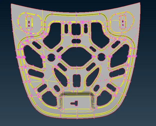
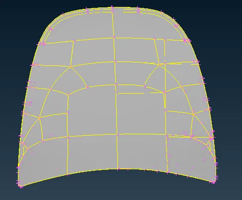
INNER PART OUTER PART
GEOMETRY PARTS:
This imported model has 5 parts
1. Inner part
2. Outer part
3. Left side hinge
4. Right side hinge
5. Centre latch
PROCEDURE:
IMPORT THE CAD MODEL TO ANSA
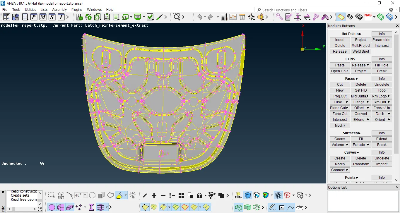
GEOMETRY CLEANUP:
After importing of cad model into ANSA, there will be many geometry errors present in the model. we have to check and clean them before meshing.
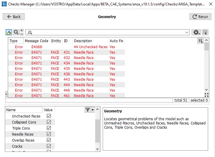
The checks manager will check the geometry and show the errors which are in the cad model. The required feature such as unchecked faces, triple cons, needle faces, cracks, collapsed cons has to be kept on so that checks manager will show the errors based on the feature as selected. There are two options for cleaning these geometry errors. These errors can be cleaned one by one approaching the error area and fixing the error by deleting cons and hotpoints. The other method is that fix the errors by ANSA itself by using fix option in the checks manager. This method is the most preferred one because it reduces time consumption.
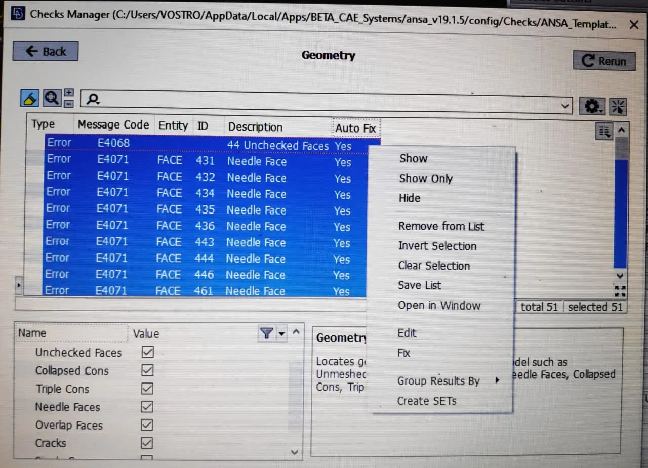
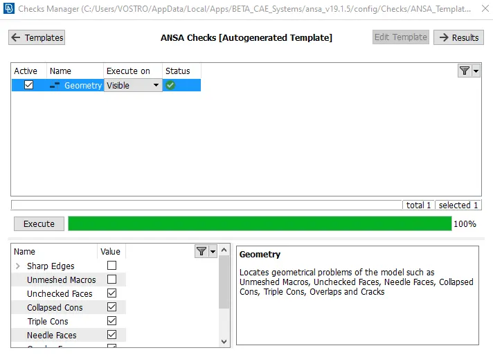
After cleaning of all errors, rerun the manager and check whether all the geometry errors are cleaned.
MIDSURFACE EXTRACTION:
Before midsurface extraction, we have to ensure that surface has a unique thickness if the thickness vary we have to separate them
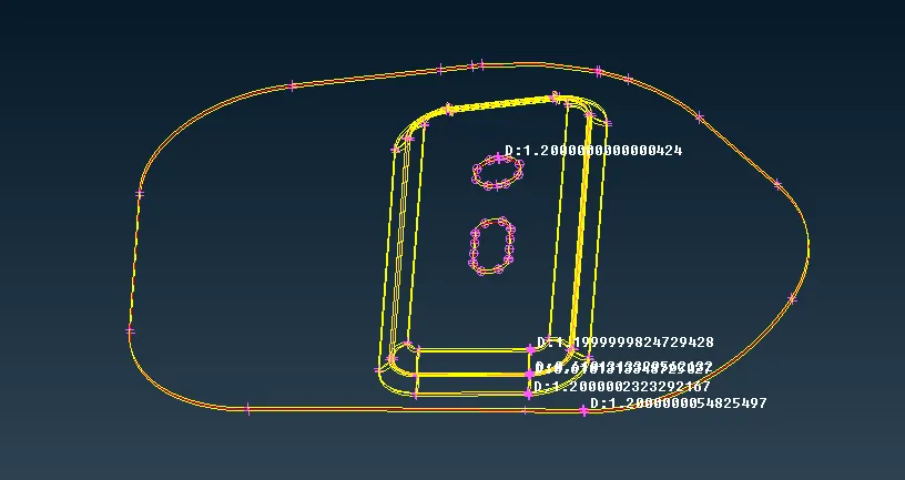
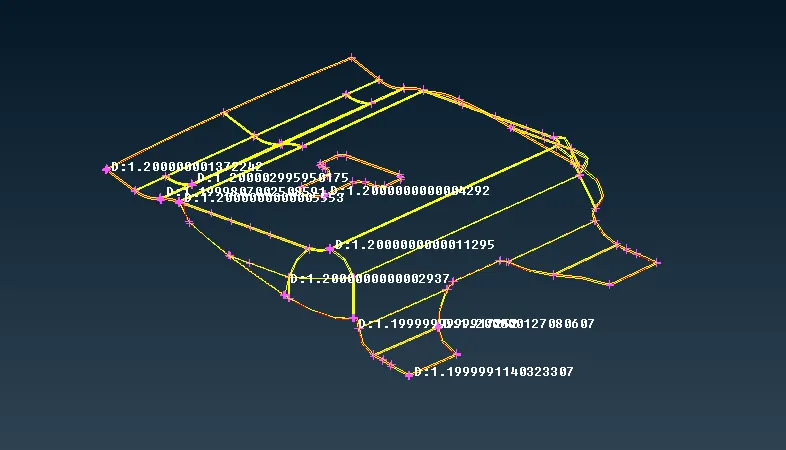
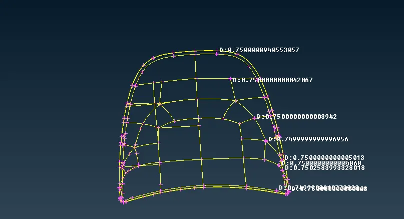
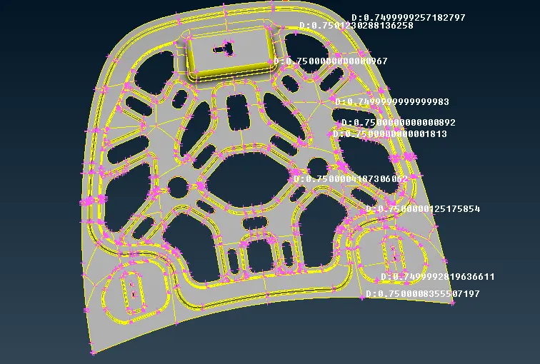
After measuring the model it has been concluded that hinges and latch has a thickness of 1.20mm, inner part and outer part has a thickness of 0.75mm.
A midsurface can be extracted by two methods:
1. MANUAL MIDSURFACE METHOD
2. AUTO MIDSURFACE METHOD
MANUAL MIDSURACE METHOD:
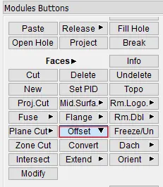
This method can be done by manually clicking the offset option and selecting the surface, the offset value has to be given when creating a midsurface. The orientation of the surface should be kept uniform, the grey color represents positive and yellow color represents negative. the grey color is always preferred while working on the model.
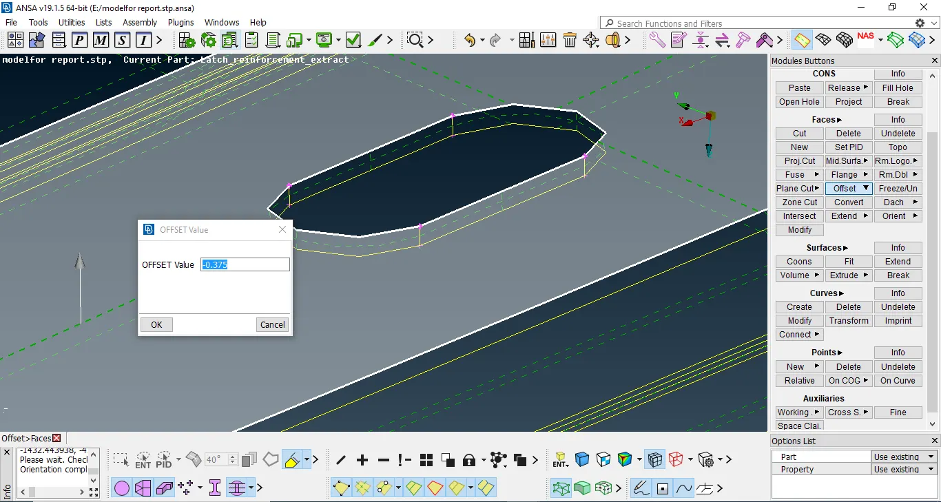
The offset value is -0.375 because we want to generate the surface in the opposite direction of the arrow.
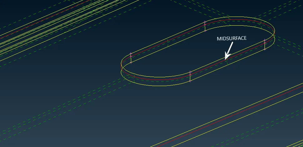
The red line indicates that midsurface has been created without deleting the parent surface, ANSA will ask whether original face has to delete or not, we have to select NO option.
AUTO MIDSURFACE METHOD:
This method can be done by selecting midsurface option under the face module, select the skin option and select the full geometry, and confirm mid location. this method can only be used when the model is closed.
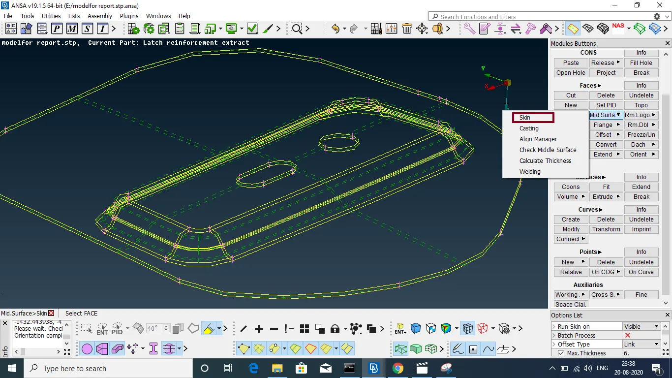
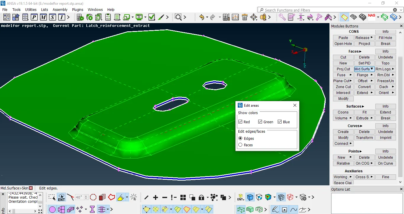
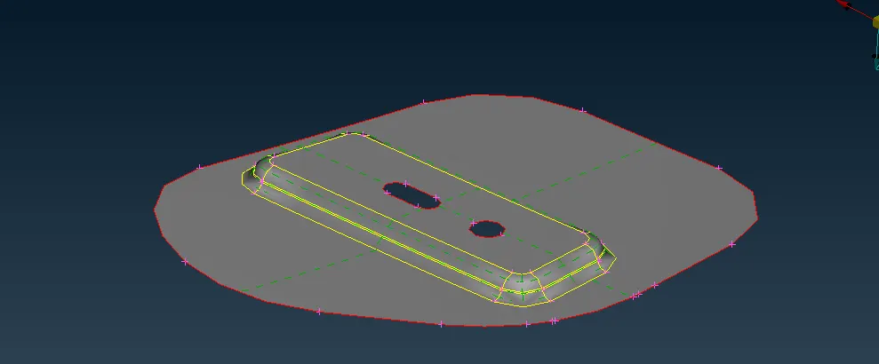
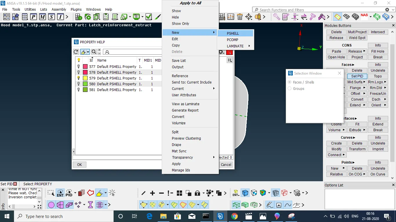
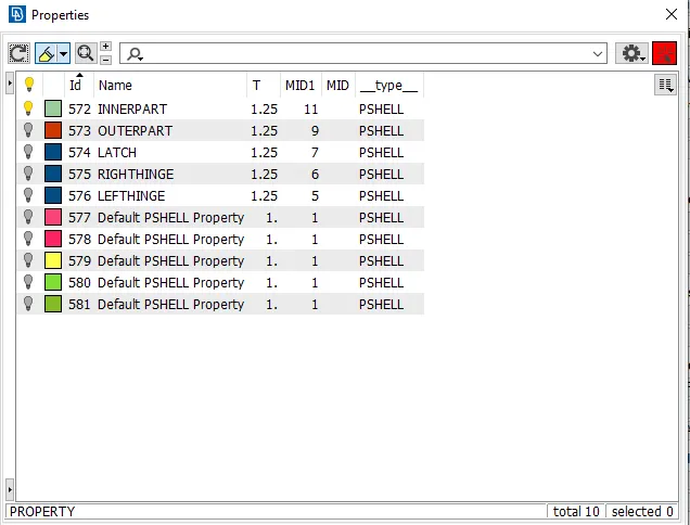
Midsurface for hinge has been generated by using an auto midplane option. the parent surface will be deleted while using the auto midplane option. likewise, midplane can be extracted for other geometry by using an auto or manual midplane method. after creating midplane for all the geometry we have to create property id for each geometry. Property id can create by selecting the SET PID option under face module button.
QUALITY CRITERIA SETUP:
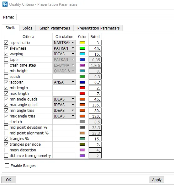
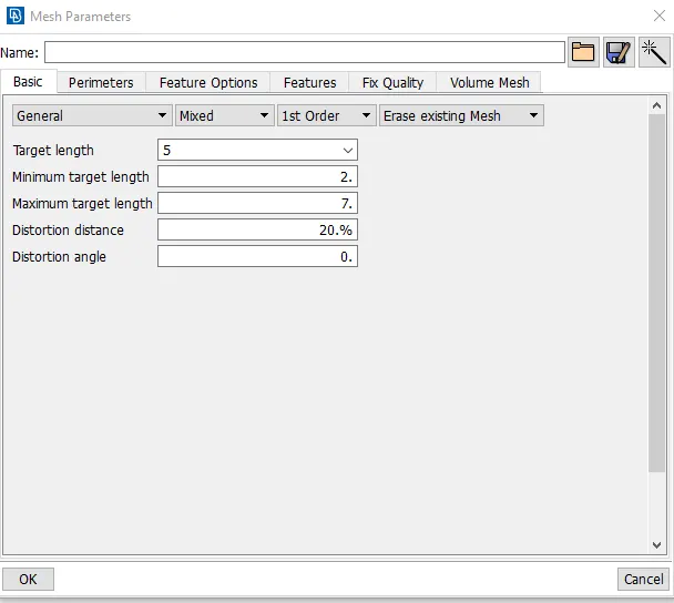
We must assign quality parameters such that meshing elements will get measured from their ideal shape. The parameters like warping, skewness, aspect ratio, etc.. have to be given in the quality criteria setup. meshing parameters also have to give before meshing such that surface will get mesh under given length.
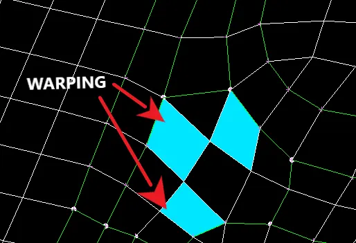
Elements failing under given quality criteria
DEFEATURING:
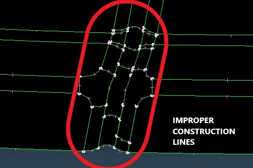
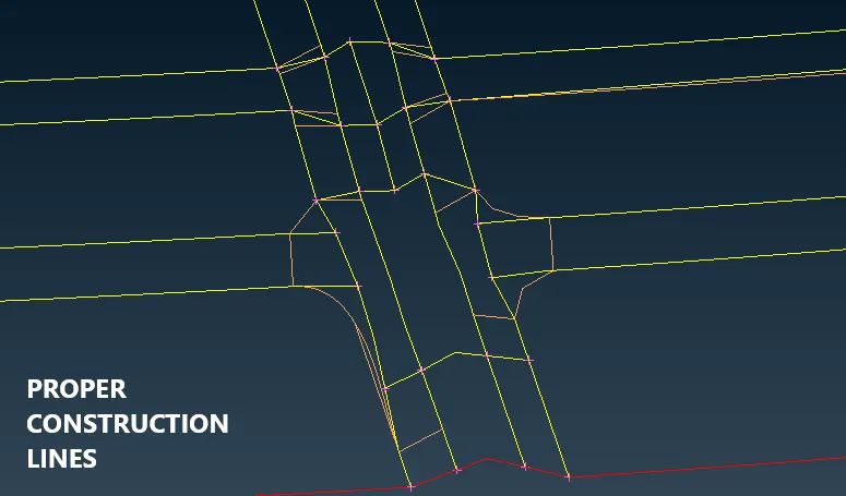
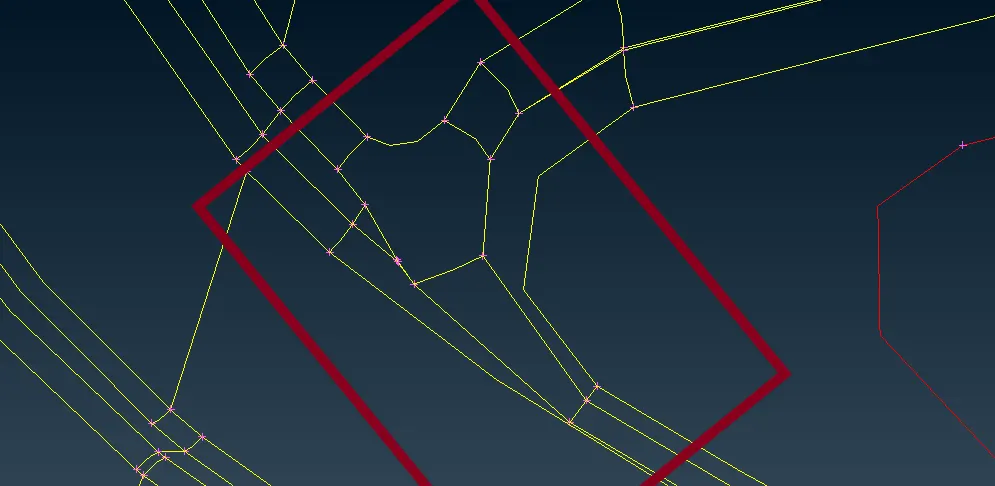
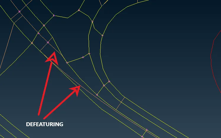
Defeaturing means removing unnecessary construction lines and curves in the CAD model because of manufacturing constraints. we have to remove them or arrange them properly for the better mesh flow without failing quality criteria. Very small entities can be a problem if you have a very small face with sharp angles, meshing might get fail. Therefore check the CAD model for very small entities and remove them before creating a mesh for it.
MESHING:
Meshing is an integral part of the engineering simulation process where complex geometries are divided into simple elements that can be used as discrete local approximations of the larger domain. It is a network that is formed of cells and points.
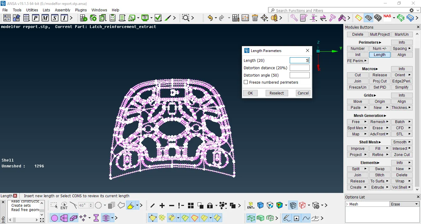
Now we can finally mesh the component after defeaturing the complex areas. there must be better mesh flow in the component. Before starting meshing we have to set perimeter elemental value as 5mm so that perimeter points will be arranged within the limit in the surface edges.
There are multiple options for meshing the surfaces
1. Best Mesh
2. Free mesh
3. Batch mesh
4. Spot mesh
5. Map mesh
We are going to use best mesh option for meshing. There are various tools used for getting better mesh flow by reconstruct the mesh and smooth them which is not good.
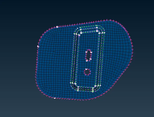
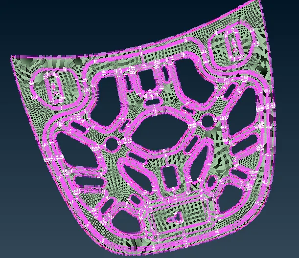
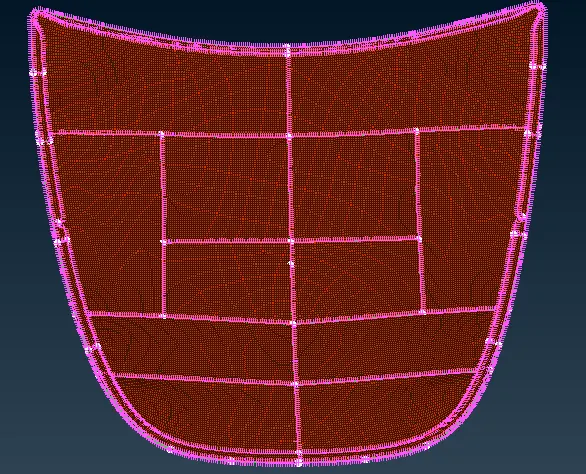
RESULTS OF MESHED PARTS
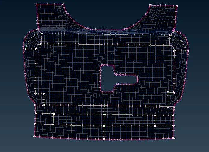
LATCH
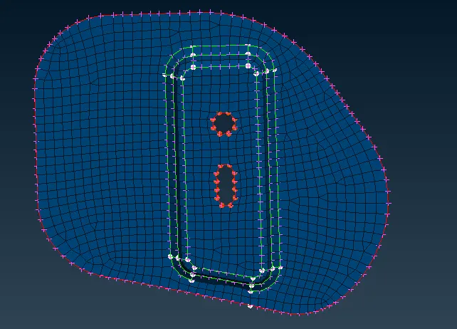
LEFT HINGE
RIGHT HINGE
INNER HOOD PART
OUTER HOOD PART
HANDLING OF TRIA ELEMENTS:
Tria elements are formed with 3 nodes, they need to handle carefully while meshing. because when we apply the loads near to fillets or holes where the trias appear, the results will not be accurate. Depending upon the geometry, even when we mesh with all quad elements sometimes we end up having rotating Quad elements. To avoid these rotating quad elements we need to smartly introduce the Tria elements.
When it comes to Tria elements, there are a few thumb rules to be followed
-
The Tria elements should never be opposite to each other
-
No Tria elements should be connected back to back
-
No Tria elements should be on the edge of the geometry
-
No Tria elements should be near the holes
-
No Tria elements should be on the feature and the fillets.
-
There should be less Tria concentration, i.e., there should be a considerable distance between Tria elements.
REFERENCE: TRIA ELEMENTS
CONCLUSION:
From the above challenge, the CAD model has been created with 2D mesh with given quality criteria and better mesh flow is created using mesh tools. some areas are compromised because of manufacturing constraints and arranged them with the proper construction lines.