2D meshing for sheet metal using FEA ANSA
Objective : The objective of this project is to create a Surface meshing on a given component.
ANSA:
The automotive industry makes extensive use of the computer-aided engineering tool known as ANSA for finite element analysis and computational fluid dynamics (CFD) analysis. BETA CAE Systems is the company that created it. A number of BETA CAE Systems subsidiaries and business agents work together to disseminate the software all over the world.
ANSA ensures that the connection between the CAD geometry and the FE mesh remains intact. This indicates that the FE meshes are superior representations of the geometric parents to which they belong. Additionally, it is simple to maintain and update any changes in the geometry by merely rewriting the updated region rather than starting from scratch to recreate the FE. This makes it straightforward to do so.
It includes many unique algorithms for meshing that are appropriate for computational fluid dynamics (CFD) simulations as well as structural models. Automatic net generation for structural analysis was the original meaning of the acronym ANSA, but the software has rapidly expanded beyond that scope. TOPO MESH, VMESH, DECK-SOLVER, MORPH, and HBLOCK are the names of the many operations that can be accomplished with the help of ANSA's broadly six menus.
ANSA contains a variety of modules of the following types:
TOPO is an abbreviation that stands for "Set of Tools for Optimizing and Polishing Geometry."
Tools that may create Surface Mesh or 2D Mesh are referred to as MESH.
VOLUME MESH is used to generate a solid or three-dimensional mesh.
SOLVER DECKS are tools that are constructed on the back of several solvers, such as ABAQUS, RADIOSS, and ANSYS, amongst others.
MORPH is an advanced tool that allows for more precise capturing of geometry during the meshing process.
Method of solving the problem:
In order to solve the problem, we will follow the approach below,
- Import the model created in CAD.
- Defining "Cons" Resolution
- A check on your geometry.
- The setup of every necessary PIDs
- Optional selection of the type of Mesh.
- The creation of mesh
1) Importing of CAD model :
- In order to import the CAD model, please follow the instructions below.
2) Defining Cons Resolution:
- The Cons resolution option in the Mesh module uses the Length parameter (the suggested Length value for cons resolution is 1).
3) Geometry check-up :
- It is necessary to perform a geometry check-up in order to determine whether or not the model contains any faults, such as unclosed faces, superimposing faces, any holes, or any geometry disorder.
- To do this operation , go to toolbar -> checks -> geometry -> visible -> execute
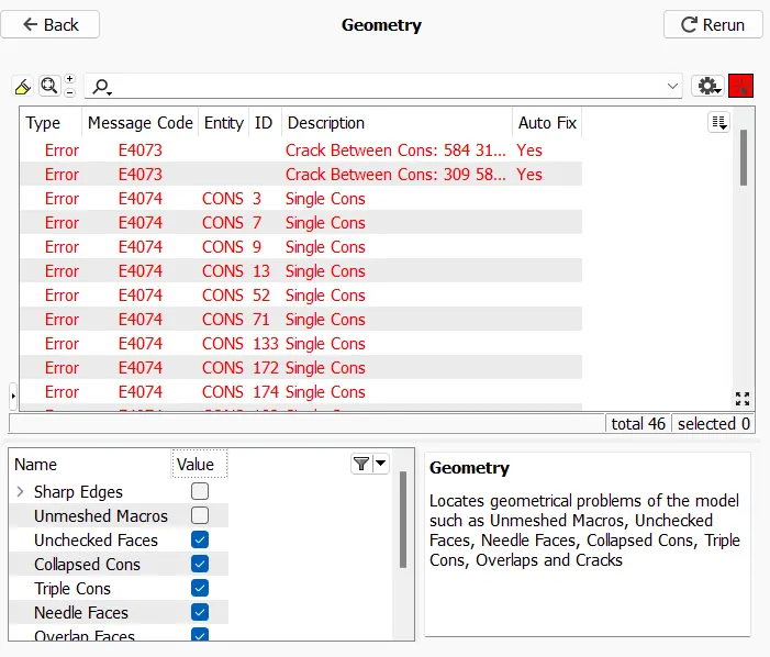
- After running geometry check up, the previous image reveals that there are quite a few mistakes. These are the mistakes that need to be rectified. If you look closely at those faults, you'll notice that there are a large number of individual problems that need to be fixed. Because single cons will be present whenever there are open surfaces or cons that share an edge with only one surface.
- After running geometry check up, the previous image reveals that there are quite a few mistakes. These are the mistakes that need to be rectified. If you look closely at those faults, you'll notice that there are a large number of individual problems that need to be fixed. Because single cons will be present whenever there are open surfaces or cons that share an edge with only one surface
-
-
4) Topo/Geometry cleanup :
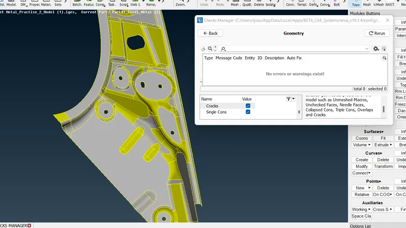
- If you want to see the location of the error that was shown in the geometry check up, you can select pick and select the con to see where it is present and see a preview of the error (a single con) in the model by clicking on it. If you want to see the location of the error that was shown in the geometry check up, you can click here.
- We will be able to see the single disadvantages thanks to the visibility tools, and we will have to eliminate the single disadvantages wherever they appear by using AUTO FIX by clicking right button.
- Using the same methodology as before, we generate surfaces wherever there is a single con by using the aforementioned methods.
5) Examine the thickness of each component.
- If the thickness is less than five or six millimetres, then we are required to remove the midsurface.
- It is not necessary to remove the midsurface if the thickness is larger than 5 or 6 millimetres.
6) Developing the midsurface of a component made from sheet metal.
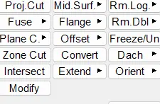
- If the components all have the same thickness, then we shall extract the midsurface using either the Skin or Offset option.
7.) Giving Quality Criteria:
- After all of that, before we can begin meshing, we need to submit the quality parameters that have been given.
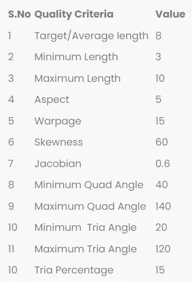
- We are required to enter values for each of these factors within the quality dialogue box.
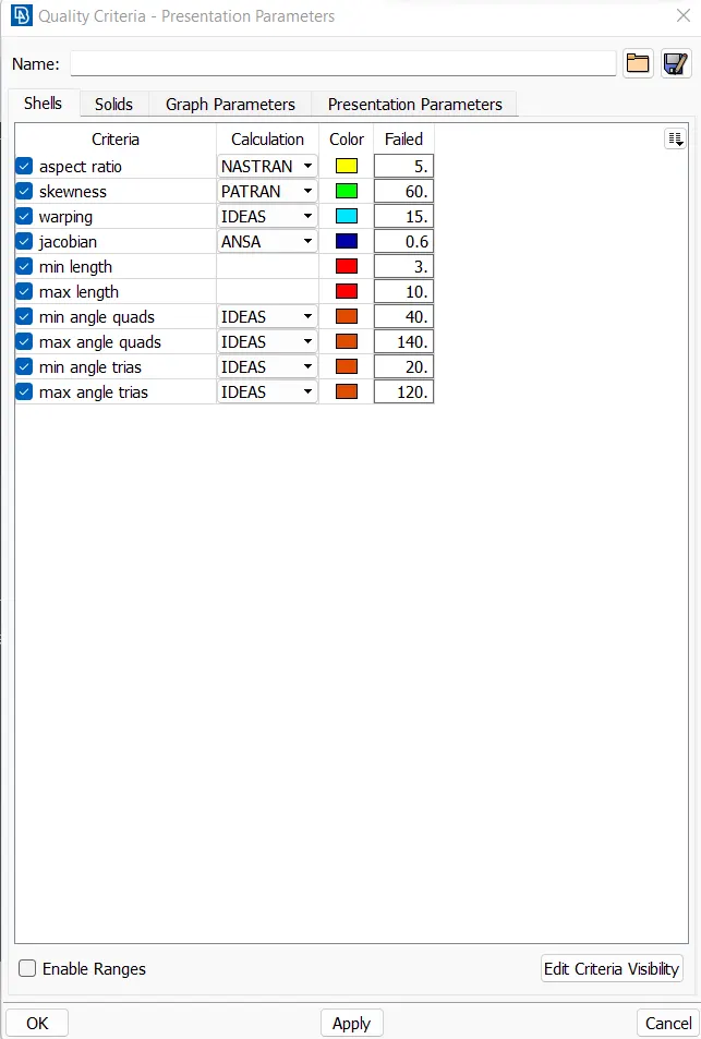
8.) Meshing:
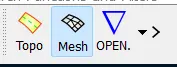
- Now that we have everything set up, the next step is meshing, and in order to do that, we need to go to the meshing module.
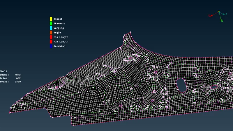
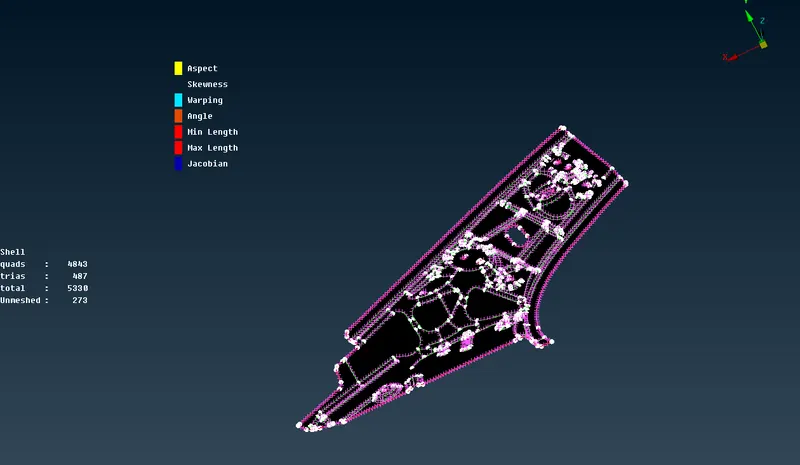
- After the meshing process, we need to ensure that there are no off elements, enhance the quality of the meshing, and have a minimum number of trias.
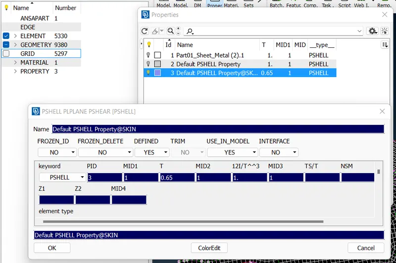
- Providing Thickness & Releasing:
-
Conclusion:-
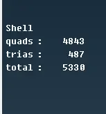
After the completion of the volumetric mesh, the number of tria elements has been determined to be 487, and the number of OFF elements has been determined to be 0.
The result of the learning is:
During this step, we learned how to import the CAD model, how to perform a geometry check-up, how to perform a topo/Geometry cleanup, how to perform the Setting-up of relevant PIDs to different parts, how to select a meshing type, and how to finally generate a surface mesh.
For refrence, ZIP file is attached