Modified on
Wrap Around Distance In Crash Analysis

Skill-Lync
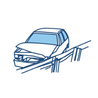
Crash analysis is mostly used to predict how a car will respond in frontal or side crashes. Two crucial factors, crashworthiness and minimal weight are taken into account when constructing any vehicle. The foundation of the car is its chassis frame. Its primary goal is to bear the maximum load for all intended operational states. This is a stage in the designing process, which can lessen the requirement for expensive destructive testing programmes. This technique has a broad use across the entire automotive sector as it lowers the price of the vehicle's actual crash testing.
Crashworthiness
The structural integrity of a car is determined by its crashworthiness. In terms of passenger safety, frame analysis, and material choice, the growing significance of a passenger car's safety makes it a pertinent area of study. The choosing of an acceptable material has grown more challenging with the development of Material Sciences and Composites. Composite materials provide greater structural strength without adding to their weight. Thus, the possibilities for application in the automobile industry grow and a wider range of analysis is made possible. Numerous research on the strength of frames or material analyses in various passenger car components have been done throughout the years.
In addition to taking a lot of time and being expensive, crash testing necessitates the destruction of a number of test vehicles. Computer simulated crash testing is one relatively recent technology that is rapidly gaining favour.
Here, a FE (Finite Element) model of the vehicle is created in place of a real vehicle and is used to conduct the various tests that were performed before utilising real vehicles.
There are a number of software programmes that can handle testing vehicles for crashes, but ANSYS is one of the most well-liked. The crash simulation is being done with Ansys software. Using the software, both static and dynamic analyses are performed.
_1663334054.png)
What is Wrap Around Distance?
When a car hits a pedestrian, the whole human body wraps around the front shape of the car and the head impacts the bonnet or the windscreen. The distance at which the head impacts the car from the ground is called the Wrap Around Distance (WAD).
To be specific the Wrap Around Distance is a measurement of the distance from the ground to the head impact zone over the outer surface of the car. The wrap-around distance is measured longitudinally in the centre of the vehicle from the ground.
_1663334138.png)
The severity of the injury caused by the frontal crash depends on the type and shape of the vehicle, speed of the vehicle and the movement of the pedestrian relative to the vehicle. In addition to these parameters, the wrap-around distance plays a major role in the safety measures for a pedestrian.
Detecting Wrap-Around Distance
During the crash analysis, based on the Wrap Around Distance (WAD), two test areas will be created namely the Child head impact zone and the Adult head impact zone. The child head impact zone is between 1000 to 1700 mm WAD and the adult head impact zone ranges between 1700 to 2100 mm WAD.
_1663334206.png)
Author

Navin Baskar
Author
Skill-Lync
Subscribe to Our Free Newsletter

Continue Reading
Related Blogs
Learn how to render a shock-tube-simulation and how to work on similar projects after enrolling into anyone of Skill-Lync's CAE courses.
09 May 2020
In this blog, read how to design the frontal BIW enclosure of a car (Bonnet) and learn how Skill-Lync Master's Program in Automotive Design using CATIA V5 will help you get employed as a design engineer.
09 May 2020
Tetrahedral is a four- nodded solid element that can be generated through the tria element by creating a volume and also through the existing volume of the geometry. These elements are used where the geometry has high thickness and complexity. The image attached below is a representation of a Tetra element. The Tetra element will have 4 triangular faces with four nodes joining them together
01 Aug 2022
A connector is a mechanism that specifies how an object (vertex, edge, or face) is connected to another object or the ground. By often simulating the desired behaviour without having to build the precise shape or specify contact circumstances, connectors make modeling simpler.
02 Aug 2022
One of the most crucial processes in carrying out an accurate simulation using FEA is meshing. A mesh is composed of elements that have nodes—coordinate positions in space that might change depending on the element type—that symbolise the geometry's shape.
03 Aug 2022
Author
Skill-Lync
Subscribe to Our Free Newsletter
Continue Reading
Related Blogs
Learn how to render a shock-tube-simulation and how to work on similar projects after enrolling into anyone of Skill-Lync's CAE courses.
09 May 2020
In this blog, read how to design the frontal BIW enclosure of a car (Bonnet) and learn how Skill-Lync Master's Program in Automotive Design using CATIA V5 will help you get employed as a design engineer.
09 May 2020
Tetrahedral is a four- nodded solid element that can be generated through the tria element by creating a volume and also through the existing volume of the geometry. These elements are used where the geometry has high thickness and complexity. The image attached below is a representation of a Tetra element. The Tetra element will have 4 triangular faces with four nodes joining them together
01 Aug 2022
A connector is a mechanism that specifies how an object (vertex, edge, or face) is connected to another object or the ground. By often simulating the desired behaviour without having to build the precise shape or specify contact circumstances, connectors make modeling simpler.
02 Aug 2022
One of the most crucial processes in carrying out an accurate simulation using FEA is meshing. A mesh is composed of elements that have nodes—coordinate positions in space that might change depending on the element type—that symbolise the geometry's shape.
03 Aug 2022
Related Courses