


Modified on
Simulating Flow Through a Centrifugal Pump Using SolidWorks

Skill-Lync
Welcome to another post in the CFD Simulation Using SolidWorks series! In this blog, we will guide you through simulating flow through a centrifugal pump using SolidWorks. This tutorial will introduce important concepts like moving reference frames, a critical aspect in CFD analysis for rotating machinery.
Whether you're taking an introduction to computational fluid dynamics or working on CFD projects for mechanical engineering, this step-by-step guide will help you understand how to simulate complex flows using SolidWorks. Let’s dive in!
Step 1: Setting Up the Geometry
We’ll begin by creating a simple impeller for our centrifugal pump. This is a mockup geometry for demonstration purposes, but it will help us understand the process.
- Start a New Part File: Open SolidWorks and create a new part. Select the Top Plane and begin by sketching a circle with a radius of 0.02 meters. This circle will form the core of your impeller.
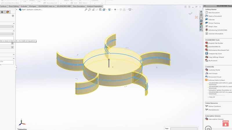
- Create the Blades: Draw an outer circle with a radius of 0.04 meters. This outer circle will guide the shape of the impeller blades. Using the arc tool, sketch your blades from the center circle to the outer circle. Since this is a simple geometry, feel free to adjust the blade shape to your liking.
- Trim and Pattern: Use the trim tool to clean up the sketch, then use the circular pattern tool to replicate the blade pattern around the circle. We’ll use five blades in this example, but you can try other variations.
- Extrude the Blades: After finishing the sketch, exit the sketch mode and use the extrude feature to give the impeller thickness. Use the mid-plane option to extrude the geometry to about 1 cm.
Step 2: Designing the Volute (Outer Casing)
Next, we will create the volute, which is the outer casing that directs the fluid flow.
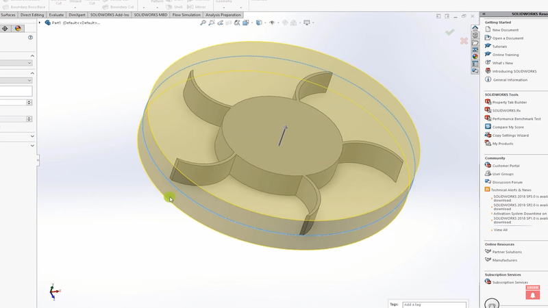
- Sketch the Volute: Go back to the Top Plane, create a new sketch, and draw a circle with a diameter of 4.5 cm. This will serve as the diameter of your volute.
- Extrude the Volute: Exit the sketch and use the extrude tool to give the volute a height of 1.5 cm. Use the mid-plane option for a symmetrical extrusion.
Tip: Make sure to uncheck the merge result option during the extrusion process. This ensures the impeller and volute are not merged into a single part.
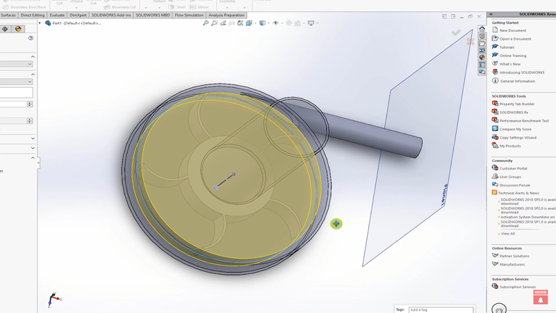
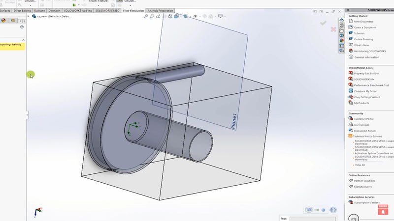
- Check the Geometry: Use the section view tool to inspect the volute and ensure that the impeller is properly positioned within it.
Step 3: Adding Inlets and Outlets
Now we’ll create the inlet runner and the outlet for the fluid flow.
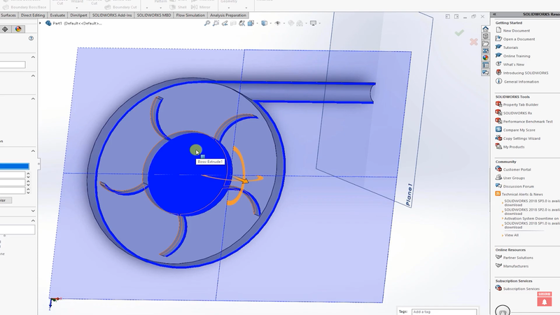
- Create the Inlet: On the top of the volute, draw a circle with a radius of 1.5 cm. This will represent the inlet runner. Extrude the inlet runner to a length of 7 cm.
- Create the Outlet: Use the Top Plane to sketch a tangent circle for the outlet. Position it such that it aligns with the flow path and extrude it using the sweep tool along a defined path.
Step 4: Creating the Rotation Zone
For simulating rotating machinery in CFD analysis software, we use a Moving Reference Frame (MRF) to simulate rotation effects without physically rotating the geometry.
- Sketch the Rotation Zone: Create a circle around the impeller, ensuring it fully encloses the impeller but does not intersect the volute. This circle will define the rotation zone.
- Extrude the Rotation Zone: Use the extrude tool and confine the extrusion within the impeller’s height using the mid-plane option. This zone will later be defined as the rotating region.
Important Note: Make sure to uncheck merge results for the rotation zone as well. This step is crucial to differentiate the rotation zone from the rest of the fluid volume.
Step 5: Setting Up the Flow Simulation
Now that the geometry is ready, let’s set up the CFD simulation in SolidWorks Flow Simulation.
- Start a New Simulation: Open the flow simulation wizard and name the project Centrifugal Pump Simulation. Select internal flow and steady-state simulation. Ensure that the time-dependent option is unchecked.
- Set Rotating Region: Define the rotating region by selecting the zone we created around the impeller. Choose the rotation speed (e.g., 1000 radians per second).
- Add Fluids: In the fluid settings, select water as the fluid. If you wish to simulate cavitation, make sure to set the proper boundary conditions. However, for this introductory CFD course, we’ll skip cavitation.
Step 6: Defining Boundary Conditions
- Inlet: Apply a pressure boundary condition at the inlet. For simplicity, we’ll set the inlet to environmental pressure.
- Outlet: Set a velocity boundary condition at the outlet. You can experiment with different values, but let’s start with 10 m/s.
Step 7: Meshing and Running the Simulation
- Mesh Setup: Use Advanced Channel Refinement to automatically refine the mesh in areas with tight geometry. This ensures the impeller and flow paths are accurately resolved.
- Run the Simulation: Before running the simulation, go to calculation control options and uncheck all convergence criteria except for iterations. Set the iteration count to 500 to ensure the solution develops properly.
- Start the Simulation: Use 16 cores if possible to speed up the calculation. Monitor the results using cut plots and flow trajectories to visualize the flow.
Conclusion
In this blog, we walked through how to simulate flow through a centrifugal pump using SolidWorks Flow Simulation. This exercise introduced key concepts such as moving reference frames, CFD meshing, and setting boundary conditions. Whether you're taking a CFD crash course or working on CFD projects for mechanical engineering, this tutorial is designed to help you get hands-on experience with SolidWorks simulations.
If you're looking to expand your skills further, consider enrolling in the Skill-Lync CFD Course or the Skill-Lync SOLIDWORKS Training. These courses provide in-depth knowledge, practical projects, and CFD certification courses to help you build a strong foundation in computational fluid dynamics.
Good luck with your simulation, and feel free to reach out with any questions. Stay tuned for more CFD tutorials in this series!
Happy Simulating!
This blog is part of our ongoing series on CFD Simulations using SolidWorks.
If you missed the previous posts, check them out here.
Would you like to have a more interactive demonstration of the above concepts?
Skill-Lync has released a FREE comprehensive course covering CFD Simulations using SolidWorks in detail! Check it out here.
Right from the user interface's fundamentals, menus and options, this course covers most aspects of the tool from a practical perspective. It even includes a certificate to add to your resume after completion!
Check out our hands-on course today and add SolidWorks to your list of skills!
Let’s get #IndustryReady together, one skill at a time!
Author
Uma Maheswari K
Author
Skill-Lync
Subscribe to Our Free Newsletter

Continue Reading
Related Blogs
Explore the fundamentals of vehicle dynamics and ultimate trends in the field from design and modeling to control with Skill Lync's exclusive course on the subject. Read about how Skill-Lync's CAE courses can help you get employed.
28 Jul 2020
In this article, we will briefly discuss the working, applications, and features of the one-dimensional systematic simulation tool, GT-Power, in Emission Control Strategy, engine calibration, hybrid vehicle modeling. Read about how Skill-Lync's CAE courses can help you get employed.
28 Jul 2020
This article offers a brief introduction to the globally accepted standard of Geometric Dimensioning and Tolerancing, and its importance for the entire manufacturing process. Read about how Skill-Lync's CAE courses can help you get employed.
28 Jul 2020
In this blog we will read about Going a step into Biomechanics and how Skill-Lync's CAE course will help you get employed.
09 May 2020
The powertrain is the most prominent source of vibrations that affects the driving experience for the people on board. This blog from Skill-Lync examines these vibrations to help enhance that experience.
21 Aug 2020
Author
Skill-Lync
Subscribe to Our Free Newsletter
Continue Reading
Related Blogs
Explore the fundamentals of vehicle dynamics and ultimate trends in the field from design and modeling to control with Skill Lync's exclusive course on the subject. Read about how Skill-Lync's CAE courses can help you get employed.
28 Jul 2020
In this article, we will briefly discuss the working, applications, and features of the one-dimensional systematic simulation tool, GT-Power, in Emission Control Strategy, engine calibration, hybrid vehicle modeling. Read about how Skill-Lync's CAE courses can help you get employed.
28 Jul 2020
This article offers a brief introduction to the globally accepted standard of Geometric Dimensioning and Tolerancing, and its importance for the entire manufacturing process. Read about how Skill-Lync's CAE courses can help you get employed.
28 Jul 2020
In this blog we will read about Going a step into Biomechanics and how Skill-Lync's CAE course will help you get employed.
09 May 2020
The powertrain is the most prominent source of vibrations that affects the driving experience for the people on board. This blog from Skill-Lync examines these vibrations to help enhance that experience.
21 Aug 2020
Related Courses


