


Modified on
Automating Valve Lift Changes with a Parametric Study in SolidWorks

Skill-Lync
Welcome back to the CFD Simulation Using SolidWorks blog series! In this post, we’ll dive into an exciting feature in SolidWorks Flow Simulation: automating valve lift changes using the parametric study option. If you're new to CFD, this post will show you how to set up a parametric study that automatically adjusts the valve lift across a range of values, saving you time and effort.
This is particularly useful if you're working on complex models where manual adjustments for each scenario would be time-consuming. So, let’s jump in and explore how to make this process smoother.
Step 1: Preparing the Model for a Parametric Study
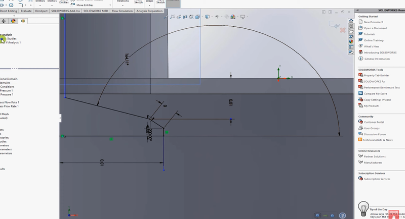
To begin, ensure that you’ve set up the dimension controlling the valve lift. If you haven’t done this yet, refer to the previous blog where we covered this step in detail.
Once the valve lift dimension is in place, don’t exit the Smart Dimensions window. We’re going to start the parametric study from here, but first, ensure you’ve run a baseline simulation. Running the baseline simulation is crucial to confirm that the model works correctly before adding more complexity.
Baseline Simulation Setup:
- Define a Total Pressure Inlet.
- Set a Static Pressure Outlet.
Once you’ve run the baseline simulation successfully, proceed to the parametric study setup.
Step 2: Setting Up the Parametric Study
Start the Parametric Study: Right-click on your Flow Analysis in the Simulation Manager and select New Parametric Study.
Add Dimension Parameter: In the parametric study window, click on Add Dimension Parameter. Select the dimension that controls the valve lift.
Define Lift Range: Choose Discrete Values and then select Range with Number. For example, set the minimum lift to 0.001 meters and the maximum lift to 0.008 meters. You can specify how many steps you want within this range (e.g., 7 values).
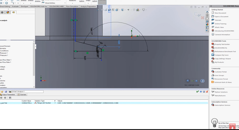
At this point, you’ve successfully set up the geometry for multiple design points, and the valve lift will change automatically across the defined range.
Step 3: Adding Output Variables
Now that the parametric study is set, you need to add output variables for the results you wish to analyze.
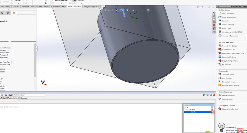
Cut Plane for Velocity: Create a Cut Plane to analyze velocity. Right-click and select Insert Cut Plane. Use the Front Plane to slice through the geometry and set velocity as the output parameter.
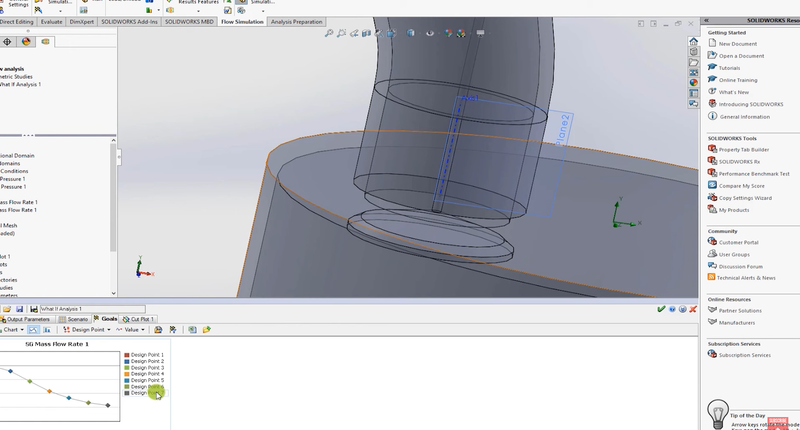
Mass Flow Rate Goal: Right-click on Goals, then select Surface Goals. Choose Mass Flow Rate for the output at the outlet. This will allow you to track how much mass flows through the valve as the lift changes.
Once these output variables are defined, go back to the parametric study window and add both the cut plot for velocity and the surface goal for mass flow rate as your output parameters.
Step 4: Adjusting the Mesh
Before running the study, it’s important to adjust the mesh for accuracy.
Edit the Mesh Definition: Right-click on Mesh and select Edit Definition. For this example, set the mesh scale to 4. You can view the basic mesh, but for the sake of simplicity, this scale should suffice for a range of design points.
Step 5: Running the Parametric Study
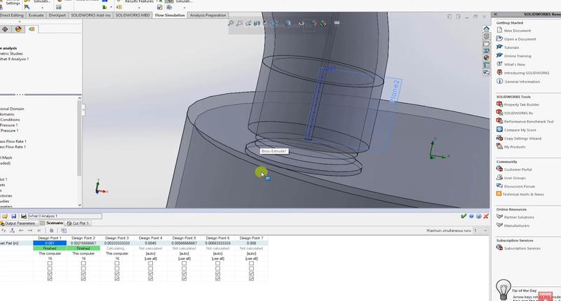
With everything set up, you can now run the parametric study:
Run the Simulation: Click the Run button to begin the simulations for all the design points. As the simulations run, you’ll notice that the valve automatically opens more as each design point completes.
Step 6: Analyzing the Results
Once the simulation is complete, you can dive into the results.
Inspecting Velocity: Start by examining the cut plane. For example, when the valve lift is set to 1 mm, you’ll notice low velocities, but as the valve lift increases, the velocity through the valve rises significantly.
Mass Flow Rate: Ensure that the mass flow rate is tracked at each design point. If it’s not displaying correctly, re-add the mass flow rate goal and re-run the simulation.
You can then export the mass flow rate data to Microsoft Excel for further analysis. Plotting the mass flow rate against the valve lift will give you valuable insights into how the flow changes with lift variation.
Step 7: Using the Data for Further Analysis
The data you gather from this study is particularly useful for more advanced models or reduced-dimensional solvers like GT Power, which are often used in engine simulations.
Plotting the Results: Once you export the data, create plots that show how the mass flow rate changes with the valve lift. If you have experimental data, you can compare it with your CFD results to validate the accuracy of your simulation.
Improving Engine Models: The insights gained from this CFD using SolidWorks study can be used to fine-tune engine models, especially in cases where mass flow rate vs. valve lift data is crucial for performance optimization.
Conclusion
This blog covered how to automate valve lift changes using the parametric study option in SolidWorks Flow Simulation. By setting up the geometry, defining output variables, and running multiple design points, you save time and gain critical insights into the performance of your system.
Whether you are looking for CFD basics for mechanical engineers or fine-tuning your model as part of the Skill-Lync CFD Course, this workflow will enhance your efficiency and understanding. These skills can be studied further at Skill-Lync SOLIDWORKS Training, where you'll develop your expertise in CFD with SolidWorks.
For more advanced topics and hands-on projects, consider enrolling in Skill-Lync's Full Course on CFD. Good luck with your project, and feel free to reach out if you have any questions!
Stay tuned for the next blog, where we’ll explore more advanced CFD topics and simulations.
Happy simulating!
This blog is part of our ongoing series on CFD Simulations using SolidWorks.
If you missed the previous posts, check them out here.
Would you like to have a more interactive demonstration of the above concepts?
Skill-Lync has released a FREE comprehensive course covering CFD Simulations using SolidWorks in detail! Check it out here.
Right from the user interface's fundamentals, menus and options, this course covers most aspects of the tool from a practical perspective. It even includes a certificate to add to your resume after completion!
Check out our hands-on course today and add SolidWorks to your list of skills!
Let’s get #IndustryReady together, one skill at a time!
Author

Alda Rovina
Author
Skill-Lync
Subscribe to Our Free Newsletter

Continue Reading
Related Blogs
Explore the fundamentals of vehicle dynamics and ultimate trends in the field from design and modeling to control with Skill Lync's exclusive course on the subject. Read about how Skill-Lync's CAE courses can help you get employed.
28 Jul 2020
In this article, we will briefly discuss the working, applications, and features of the one-dimensional systematic simulation tool, GT-Power, in Emission Control Strategy, engine calibration, hybrid vehicle modeling. Read about how Skill-Lync's CAE courses can help you get employed.
28 Jul 2020
This article offers a brief introduction to the globally accepted standard of Geometric Dimensioning and Tolerancing, and its importance for the entire manufacturing process. Read about how Skill-Lync's CAE courses can help you get employed.
28 Jul 2020
In this blog we will read about Going a step into Biomechanics and how Skill-Lync's CAE course will help you get employed.
09 May 2020
The powertrain is the most prominent source of vibrations that affects the driving experience for the people on board. This blog from Skill-Lync examines these vibrations to help enhance that experience.
21 Aug 2020
Author
Skill-Lync
Subscribe to Our Free Newsletter
Continue Reading
Related Blogs
Explore the fundamentals of vehicle dynamics and ultimate trends in the field from design and modeling to control with Skill Lync's exclusive course on the subject. Read about how Skill-Lync's CAE courses can help you get employed.
28 Jul 2020
In this article, we will briefly discuss the working, applications, and features of the one-dimensional systematic simulation tool, GT-Power, in Emission Control Strategy, engine calibration, hybrid vehicle modeling. Read about how Skill-Lync's CAE courses can help you get employed.
28 Jul 2020
This article offers a brief introduction to the globally accepted standard of Geometric Dimensioning and Tolerancing, and its importance for the entire manufacturing process. Read about how Skill-Lync's CAE courses can help you get employed.
28 Jul 2020
In this blog we will read about Going a step into Biomechanics and how Skill-Lync's CAE course will help you get employed.
09 May 2020
The powertrain is the most prominent source of vibrations that affects the driving experience for the people on board. This blog from Skill-Lync examines these vibrations to help enhance that experience.
21 Aug 2020
Related Courses


