


Modified on
Creating a Geometry for Engine Valve Analysis in SolidWorks: A Step-by-Step Guide

Skill-Lync
Welcome to another blog in the CFD Simulation Using SolidWorks series! In this post, we’ll explore how to create geometry for an engine valve analysis in SolidWorks. This tutorial covers the fundamental steps of creating a valve, intake port, and related reference geometry, using a simplified approach. Whether you're a beginner or a mechanical engineer seeking to understand computational fluid dynamics basics, this guide is for you.
Let’s get started!
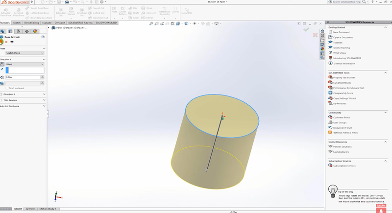
Step 1: Creating the Cylinder Geometry
- Open a New Part: Start by clicking on New and open a new part file in SolidWorks.
- Sketch the Cylinder: Select the Top Plane and create a sketch. We’ll start with a circle that represents the engine cylinder, and I’ll set the radius to 0.05 meters.
- Extrude the Cylinder: Go to the Features tab and select Extrude. Extrude the circle in the downward direction by 10 cm. This will form the base geometry for our engine cylinder.
Step 2: Creating the Intake Port
Next, we’ll add the intake port, which is an essential part of this engine valve model.
- Select the Front Plane: Click on the Front Plane, and then select the Sketch tool.
- Use the Line Tool: Using the Line tool, draw the path of the intake port. This will represent the approximate path through which air enters the cylinder. Since we’re working with a made-up geometry, you can adjust the path as needed. Apply a fillet of 0.04 meters to smoothen the path.
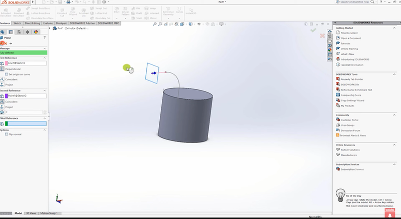
Pro Tip: If the port looks too large, go back to the sketch, and adjust the dimensions. For instance, change the diameter to 0.025 meters for a better fit.
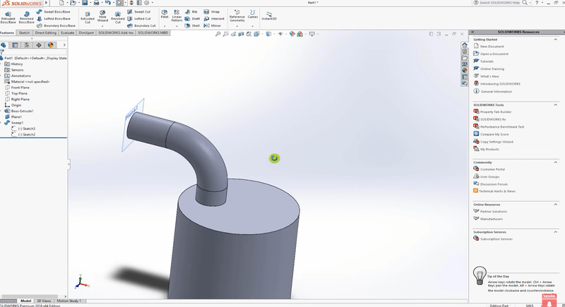
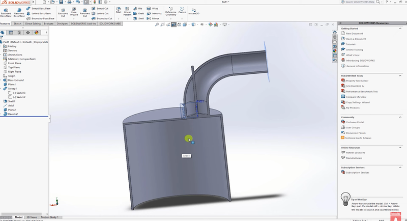
Step 3: Adding Thickness with the Shell Feature
Let’s add some thickness to our geometry.
- Use the Shell Option: Select both the top and bottom faces of the cylinder and apply the Shell feature with a thickness of 0.02 meters. This hollows out the model, ensuring it behaves more like a real engine valve with proper wall thickness.
- Use the Sweep Tool: Exit the sketch and go to the Features tab. Use the Sweep tool to construct the intake port. Select the circle for the profile and the path you just drew to create the intake port.
- Check with Section View: Use the Section View tool to inspect the shell and ensure everything looks correct.
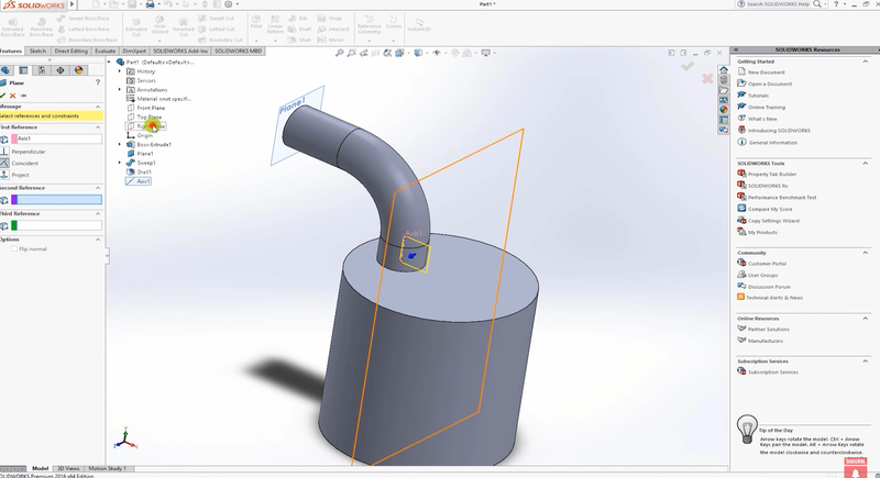
Step 4: Creating Reference Geometry for the Valve
To position the valve correctly, we’ll need to create reference geometry.
- Create an Axis: In the Reference Geometry tab, select Axis. Click on the cylindrical face of the engine cylinder, and SolidWorks will generate an axis through its center.
- Create a Plane: Next, go back to Reference Geometry and create a Plane. Use the Right Plane and the axis we just created as references to define the new plane.
Step 5: Sketching the Valve
Now that we’ve set up our reference geometry, it’s time to draw the valve.
- Start a New Sketch: Select the newly created plane and click Sketch. Using the Line tool, sketch the basic outline of the valve. This includes the valve body and the valve lip region, which you can adjust based on your model’s dimensions.
- Position the Valve: Since this is a made-up geometry, the exact dimensions are not critical, but ensure the valve is aligned with the axis created earlier. You can always refine the valve position using Smart Dimensions.
Step 6: Creating the Valve with Revolve
Now, let’s give the valve its 3D shape.
- Use the Revolve Tool: Once the valve sketch is complete, go to the Features tab and use the Revolve tool. For the axis of revolution, select the axis created in Step 4.
- Inspect the Valve: Once the revolve operation is done, the valve will be created. Use the Section View to inspect the valve and ensure it is properly positioned within the engine.
Tip: You can modify the valve position to simulate different valve openings, such as 1mm, 2mm, or 3mm. This allows you to model valve operations more realistically.
Step 7: Refining the Design and Setting Up for Analysis
To refine the design further, you can go back and adjust the Smart Dimensions for more accurate modeling. This process is particularly useful if you're aiming to integrate this setup with CFD using SolidWorks.
- Move the Valve: To test different scenarios, adjust the valve opening by moving it in 1mm increments. This will allow you to simulate different flow behaviors through the valve.
- Prepare for Analysis: Once the model is complete, you can proceed to set it up for CFD analysis. This step is critical for those looking to deepen their knowledge of computational fluid dynamics basics. In fact, if you're enrolled in the Skill-Lync CFD Course, you’ll likely cover these concepts in greater depth.
Conclusion
In this tutorial, we’ve created a simplified model of an engine valve with intake ports using SolidWorks. By following the steps outlined here, you can use this model to explore CFD basics for mechanical engineers or refine it for more complex analyses. The Skill-Lync SOLIDWORKS Training program offers a comprehensive approach to mastering these techniques, and this blog provides an essential foundation.
As part of your challenge, explore moving the valve by different increments and conducting a CFD simulation to analyze flow behavior. For more detailed instructions and advanced topics, be sure to check out Skill-Lync's Full Course on CFD with SolidWorks.
If you have any questions or need further guidance, feel free to reach out. Stay tuned for the next post in this series, where we’ll explore advanced analysis techniques in SolidWorks.
Happy Simulating!
This blog is part of our ongoing series on CFD Simulations using SolidWorks.
If you missed the previous posts, check them out here.
Would you like to have a more interactive demonstration of the above concepts?
Skill-Lync has released a FREE comprehensive course covering CFD Simulations using SolidWorks in detail! Check it out here.
Right from the user interface's fundamentals, menus and options, this course covers most aspects of the tool from a practical perspective. It even includes a certificate to add to your resume after completion!
Check out our hands-on course today and add SolidWorks to your list of skills!
Let’s get #IndustryReady together, one skill at a time!
Author
Uma Maheswari K
Author
Skill-Lync
Subscribe to Our Free Newsletter

Continue Reading
Related Blogs
Explore the fundamentals of vehicle dynamics and ultimate trends in the field from design and modeling to control with Skill Lync's exclusive course on the subject. Read about how Skill-Lync's CAE courses can help you get employed.
28 Jul 2020
In this article, we will briefly discuss the working, applications, and features of the one-dimensional systematic simulation tool, GT-Power, in Emission Control Strategy, engine calibration, hybrid vehicle modeling. Read about how Skill-Lync's CAE courses can help you get employed.
28 Jul 2020
This article offers a brief introduction to the globally accepted standard of Geometric Dimensioning and Tolerancing, and its importance for the entire manufacturing process. Read about how Skill-Lync's CAE courses can help you get employed.
28 Jul 2020
In this blog we will read about Going a step into Biomechanics and how Skill-Lync's CAE course will help you get employed.
09 May 2020
The powertrain is the most prominent source of vibrations that affects the driving experience for the people on board. This blog from Skill-Lync examines these vibrations to help enhance that experience.
21 Aug 2020
Author
Skill-Lync
Subscribe to Our Free Newsletter
Continue Reading
Related Blogs
Explore the fundamentals of vehicle dynamics and ultimate trends in the field from design and modeling to control with Skill Lync's exclusive course on the subject. Read about how Skill-Lync's CAE courses can help you get employed.
28 Jul 2020
In this article, we will briefly discuss the working, applications, and features of the one-dimensional systematic simulation tool, GT-Power, in Emission Control Strategy, engine calibration, hybrid vehicle modeling. Read about how Skill-Lync's CAE courses can help you get employed.
28 Jul 2020
This article offers a brief introduction to the globally accepted standard of Geometric Dimensioning and Tolerancing, and its importance for the entire manufacturing process. Read about how Skill-Lync's CAE courses can help you get employed.
28 Jul 2020
In this blog we will read about Going a step into Biomechanics and how Skill-Lync's CAE course will help you get employed.
09 May 2020
The powertrain is the most prominent source of vibrations that affects the driving experience for the people on board. This blog from Skill-Lync examines these vibrations to help enhance that experience.
21 Aug 2020
Related Courses


