Exploring Object Snap Tracking and Polar Tracking in AutoCAD
Discover how Object Snap Tracking and Polar Tracking in AutoCAD enhance precision for civil engineering projects. Learn to create accurate alignments and angular layouts with tools essential for AutoCAD for civil engineering, CAD programs, and AutoCAD training in this blog.
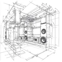
Welcome back to AutoCAD Essentials for Civil Engineers blog series. Object Snap Tracking and Polar Tracking are two of the most versatile tools in AutoCAD for civil engineering. These features allow engineers to create precise alignments and designs by snapping to predefined geometric points. In this blog, we delve into these tools and their applications, showcasing how they enhance drafting efficiency.
Object Snap Tracking: Simplifying Complex Drafting
Object Snap Tracking is a feature that allows you to track points orthogonally or at specific angles relative to existing geometries.
How to Enable: Press F11 or activate it from the status bar.
Applications:
- Orthogonal Tracking: Useful for aligning objects at 0°, 90°, or 270°.
- Intersection Tracking: Snap to the intersection of midpoints or endpoints from different objects.
- Example: Track the midpoints of two lines and create a circle at their intersection. This is a common application in civil CAD programs for structural drafting.
Polar Tracking: Aligning at Angles
Polar Tracking allows you to draw lines or objects at specific incremental angles, making it a powerful tool in AutoCAD online courses with certificates.
Steps to Use Polar Tracking:
- Enable Polar Tracking using F10.
- Set incremental angles (e.g., 30°, 45°, or custom angles).
- Use these increments to align your objects.
- Practical Example: Draft lines at 30° increments for precise angular layouts in AutoCAD civil basic projects. This is particularly helpful in designing bridges, roads, or angular layouts in CAD civil drawings.
Combining Object Snap and Polar Tracking
You can combine these tools for advanced drafting scenarios:
- Track with Polar Settings: Use Polar Tracking to align objects at specific angles while snapping to endpoints or midpoints using Object Snap.
- Example: Create a line at a 60° angle from an existing point while snapping to a predefined geometric center.
Pro Tips for Polar Tracking
- Use relative tracking for angles measured from the last segment.
- Customize additional angles for specific requirements, such as tracking at 15° or 12° increments.
Quick Guide to Function Keys in AutoCAD
AutoCAD provides a range of function keys to enhance your drafting experience:
- F1: Help
- F2: Text history
- F3: Object Snap on/off
- F10: Polar Tracking on/off
- F11: Object Snap Tracking on/off
- F12: Dynamic Input on/off
These shortcuts are indispensable for anyone pursuing a Skill-Lync AutoCAD Course or working on CAD software for civil engineers.
Conclusion
Object Snap Tracking and Polar Tracking are game-changers in AutoCAD for civil engineering online courses. They not only enhance precision but also streamline the drafting process, making them essential for professionals and students alike. By mastering these tools, you’ll be equipped to tackle complex designs with ease, whether you’re working on AutoCAD 2024 projects or advancing your skills through a Skill-Lync Autocad Training.
This blog is part of our ongoing AutoCAD Design Series. If you missed the previous posts, check them out here.
Would you like to have a more interactive experience going through the AutoCAD essentials?
Skill-Lync has released a FREE comprehensive course covering AutoCAD Essentials for Civil Engineers in detail! Check it out here.
If you’re looking to go deeper into AutoCAD Essentials check out Skill-Lync’s AutoCAD certification course.
Check out our hands-on course today and add AutoCAD to your list of skills!
Let’s get #IndustryReady together, one skill at a time!