Air standard Cycle
- AIM : Write code that can solve an otto cycle and make plots for it.
-
GOVERNING EQUATIONS :
- pV = mRT (ideal gas equation). `=> PV^gamma = C`
- thermal efficiency = `[1-frac{1}{(r)^(gamma-1)}]100`
- non-dimensional equation for change in piston cylinder volume , `frac{V}{V_c}=1+frac{1}{2}(r_c-1)[R+1-costheta-(R^2-sin^2theta)^frac{1}{2}]`
- OBJECTIVES OF THE PROJECT :
- creating a PV diagram for air-standard otto cycle using ideal gas equation.
- getting output the thermal efficiency of the engine for air-standard otto cycle.
- BODY OF THE CONTENT :
EXPLANATION OF THEORY OTTO CYCLE:
An air-standard cycle(Ideal Gas Cycle) that provides an estimation for the actual engine cycle. The accurate analysis of IC engine processes is very complicated, to understand it well, it is advantageous to analyze the performance of an Idealized closed cycle. There were different types of air standard cycles,(carnot cycle,Otto cycle, Diesel cycle,Dual cycle,Brayton cycle.)
Here we discuss an Air-Standard Otto Cycle.
Otto cycle is also known as a ‘constant volume cycle’. The operating cycle of an IC engine can be broken down into a sequence of separate processes Intake, Compression, Combustion, Expansion & Exhaust. Actual IC Engine does not operate on an ideal thermodynamic cycle that is operated on an open/actual cycle.
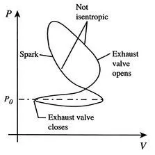 (actual otto cycle)
There were some assumption was made for air standard cycle as below :
- The working medium is a perfect gas throughout, it follows the law pV = mRT(ideal gas equation).
- The working fluid is a fixed mass of air either contained in a closed system or flowing at constant rate around a closed circuit.
- The physical constants of the working medium are the same as those of air at standard atmospheric condition,i.e, molecular weight = 29,Cp = 1.005 kJ/kg.K, Cv = 0.718 kJ/kg.K, and γ = 1.4 .
- The working medium does not undergo any chemical change throughout the cycle.
- The compression and expansion processes are reversible adiabatic (isentropic), i.e, There are no loss or gain of entropy. Because the operation of the engine is frictionless. ( **This process is reversible,but if there is friction then, the process is irreversible.**)
AIR-STANDERD OTTO CYCLE (CONSTANT VOLUME CYCLE) :
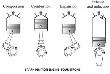
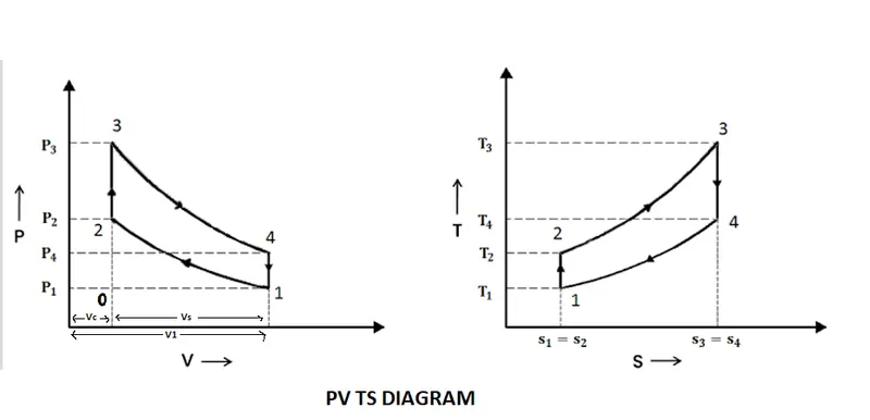
There are four processes in the cycle :
- Isentropic (reversible adiabatic) compression process (PVγ= C )
- Constant volume (Isochoric) heat addition ( kJ/kg of air )
- Isentropic (reversible adiabatic) Expansion (PVγ= C )
- Constant volume of heat rejection. ( kJ/kg of air )
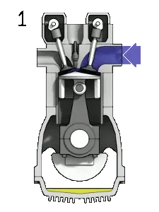
Process 0–1 intake stroke
A mass of air (working fluid) is drawn into the cylinder, from 0 to 1, at atmospheric pressure (constant pressure) through the open intake valve, while the exhaust valve is closed during this process. The intake valve closes at point 1.
Process 1–2 compression stroke
Piston moves from crank end (BDC, bottom dead centre and maximum volume) to cylinder head end (TDC, top dead centre and minimum volume) as the working gas with initial state 1 is compressed isentropically to state point 2, through compression ratio (V1/V2).Generally the compression ratio is around 9–10:1 (V1:V2) for a typical engine.
Process 2–3 ignition phase
The piston is momentarily at rest at TDC. During this instant, which is known as the ignition phase, the air/fuel mixture remains in a small volume at the top of the compression stroke. Heat is added to the working fluid by the combustion of the injected fuel, with the volume essentially being held constant. The pressure rises and the ratio (P3/P2) is called the "explosion ratio".
Process 3–4 expansion stroke
The increased high pressure exerts a force on the piston and pushes it towards the BDC. Expansion of working fluid takes place isentropically and work is done by the system on the piston. The volume ratio (V4/V3) is called the "isentropic expansion ratio". (For the Otto cycle the compression ratio (V1/V2) is same. Mechanically this is the expansion of the hot gaseous mixture in the cylinder known as expansion (power) stroke.
Process 4–1 idealized heat rejection
The piston is momentarily at rest at BDC. The working gas pressure drops instantaneously from point 4 to point 1 during a constant volume process as heat is removed.
Process 1–0 exhaust stroke
The exhaust valve opens at point 1. As the piston moves from "BDC" (point 1) to "TDC" (point 0) with the exhaust valve opened, the gaseous mixture is vented to the atmosphere and the process starts anew.
NOMENCLATURE :
r = Compression ratio
`V_c =`clearance volume
`V_s =` stroke volume
`C_p`= specific heat at constant pressure , `frac{kJ}{kg.K}`
`C_v` = specific heat at constant volume , `frac{kJ}{kg.K}`
`gamma` = ratio of specific heats, `frac{C_p}{C_v}`
`m` = mass in `kg`
`T` = temp. in `K`
`P` = pressure in `pa`
DERIVATION :
r = Compression ratio = Volume before compression / Volume after compression
`:. r = frac{V1}{V2} = frac{V_s + V_c}{Vc}`
`r_e` = Expansion ration = Volume after expansion / Volume before expansion
`:. r_e = frac{V_4}{V_3 } = frac{V_1}{V_2} = r , :' V_4=V_1 & V_3=V_2`
so, in otto cycle compression ratio are same.
1] 1-2 adiabatic or isentropic compression process (`PV^gamma = C`)
`:. P_1V_1^gamma = P_2V_2^gamma`
`:. frac{V_1^gamma}{V_2^gamma}=frac{P_2}{P_1}`
`(frac{V_1}{V_2})^gamma=frac{P_2}{P_1}`
`:. (r)^gamma=frac{P_2}{P_1}` .......(`I`) `:' (frac{V_1}{V_2}) = r`
so, similarly relation between temperature vs volume,
`:. frac{T_2}{T_1}=(r)^(gamma-1).....(II)`
2] 2-3 H.S at constant volume
`:'` heat = mass x sp. heat x temp.diff.
Heat Supplied = `m xx C_v xx (T_3-T_2)`
H.S = `1 xx C_v xx (T_3-T_2) .......(III)`
according to the Gas law, `frac{PV}{T} = C`
`:. frac{P_2V_2}{T_2}=frac{P_3V_3}{T_3}` `( :. V_2 = V_3)`
`:. frac{P_2}{T_2}=frac{P_3}{T_3}......(IV)`
3] 3-4 adiabatic or isentropic expansion process (`PV^gamma = C`)
so, similarly,
`:. frac{P_3}{P_4}=(r)^gamma ......(V)` & `:. frac{T_3}{T_4}=(r)^(gamma-1)............(VI)`
4] 4-1 H.R. at constant volume
Heat Rejected = `1 xx C_v xx (T_4-T_1) ........... (VII)` &
`:. frac{P_4}{T_4}=frac{P_1}{T_1} .......(VIII)`
Air Standard Effi. or thermal efficiency= [W.D /H.S] x 100
= [H.S - H.R/H.S] X 100
= [ 1 - (H.R./H.S)] X 100
= `[ 1 - frac{C_v(T_4-T_1)}{C_v (T_3-T_2)}] 100`
= `[ 1 - frac{(T_4-T_1)}{(T_3-T_2)}] 100` .......(1)
from equation (`III`),`frac{ T_2}{T_1} = (r)^(gamma-1)` `:. T_2 = T_1(r)^(gamma-1)`
from equation (`VI`), `frac{T_3}{T_4} = (r)^(gamma-1), :. T_3 = T_4(r)^(gamma-1)`
`:.`A.S.E. = `[ 1 - frac{(T_4-T_1)}{T_4(r)^(gamma-1)-T_1(r)^(gamma-1)}]100`
`:.`A.S.E. = `[1-frac{(T_4-T_1)}{(r)^(gamma-1)(T_4-T_1)}]100`
`:.`A.S.E = `[1-frac{1}{(r)^(gamma-1)}]100`
ENGINE KINEMATICS :
The volume of the piston cylinder can be determined as a function of crank angle from the compression ratio, the stroke, bore and connecting rod length. The geometric parameters of the piston cylinder are represented in Figure.
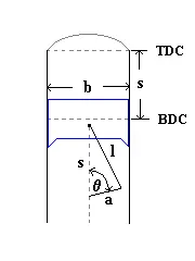
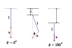
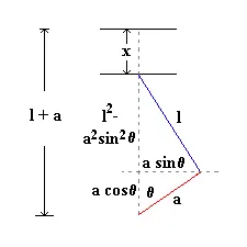
Engine slider--crank geometry
Where,
b = bore
s = stroke
l = connecting rod length
- theta = crank angle
r_c = compression ratio
a = crank radius (`= frac{s}{2}`)
`R = frac{l}{a}`
Top dead center refers to the position of the crank shaft at an crank angle of 0o. This position is otherwise known as the clearance volume, Vc. At bottom dead center the crank angle is at 180 o. In this position the cylinder volume is at its maximum, V. The difference between the maximum and minimum volume, V- Vc, is defined as the displacement volume, Vd. The displacement volume can also be represented as a function of the bore and stroke:
`V_d = frac{pi}{4}b^2s ...... 1`
At a given crank angle the volume is given by,
`V =V_c+frac{pi}{4}b^2s ......2`
now, using geometry relationship,
`s = a+l-[(l^2-a^2sin^2theta)^(frac{1}{2})+acostheta]........3`
The compression ratio is defined as the ratio between the maximum and minimum volume,
`r_c = frac{V}{V_c)`
Substituting equation 2,
`r_c = 1+frac{V_d}{V_c}........4`
Solving for `V_c` results in,
`V_c = frac{V_d}{r_c-1}.........5`
Substituting equations (3,5) in to (2),
`V=frac{V_d}{r_c-1}+frac{V_d}{2}[1+R-costheta-(R^2-sin^2theta)^frac{1}{2}].......6`
`:. frac{V}{V_d}=frac{1}{r_c-1}+frac{1}{2}[1+R-costheta-(R^2-sin^2theta)^frac{1}{2}].......7`
The final form of the Slider-Crank model is given as a non-dimensional relationship in form of `frac{V}{V_c}`ratio,is `frac{V}{V_c}=1+frac{1}{2}(r_c-1)[R+1-costheta-(R^2-sin^2theta)^frac{1}{2}]......8`
5. MATLAB code
# INPUTS ( plotting PV diagram & finding thermal effi.)
% plotting PV diagram & finding thermal effi. for air stander otto cycle.

clear all
close all
clc

% Input variable
gamma = 1.4;
t3 = 2300;          % (temp is rising during combustion)  % temp. in K.

% engine geometric parameters
% all dimension are in meter.
bore = 0.1;         % bore dia
stroke = 0.1;       % stroke length
con_rod = 0.15;     % connecting rod length
cr = 12;            % compression ratio (unitless)

% calculating the swept volume and the clearance volume
v_s = ((pi/4)*bore^2)*stroke;
v_c = v_s/(cr-1);

% variables at state point 1
p1 = 101325;    % taken atmospheric pressure in pa.
t1 = 500;       % temp. in K.
v1 = v_s + v_c;     % whole volume in the cylinder

% variables at state point 2
%p2v2^gamma = p1v1^gamma (isentropic compression prosses)
% so, p2 = p1 (v1/v2)^gamma = p1*cr^gamma
p2 = p1*cr^gamma;
v2 = v_c;
% according to the ideal gas law
% p1v1/t1 = p2v2/t2
t2 = p2*v2*t1 / (p1*v1);

% variable at state point 3
v3 = v2;    % constant volume heat addition
% p3v3^gamma = p2v2^gamma
p3 = p2*t3/t2;      % t3 as input variable

% variable at state point 4
v4 = v1;     % isentropic expansion prosses
% p3v3^gamma = p4v4^gamma
p4 = p3*(v3/v4)^gamma;

% plotting line p1 to p2 using function 'engine_kinematics'
v_compression = engine_kinematics(bore,stroke,con_rod,cr,180,360);
constant_c = p1*v1^gamma;
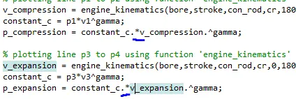
p_compression = constant_c./v_compression.^gamma;

% plotting line p3 to p4 using function 'engine_kinematics'
v_expansion = engine_kinematics(bore,stroke,con_rod,cr,0,180);
constant_c = p3*v3^gamma;
p_expansion = constant_c./v_expansion.^gamma;

% finding thermal efficiency of engine
effi = [1-(1/(cr)^(gamma-1))]*100


figure(1)
hold on
plot(v1,p1,'*','color','b')
text(v1,p1,'1','FontSize',14)
plot(v2,p2,'*','color','b')
text(v2,p2,'2','FontSize',14)
plot(v3,p3,'*','color','b')
text(v3,p3,'3','FontSize',14)
plot(v4,p4,'*','color','b')
text(v4,p4,'4','FontSize',14)
plot(v_compression,p_compression)
plot(v_expansion,p_expansion)
plot([v2 v3],[p2 p3])
plot([v4 v1],[p4 p1])
xlabel ('volume (m^3)')
ylabel (' pressure ^ (pa)' )
grid on


% to see how cylinder volume is change as per crank angle
figure(2)
theta1 = linspace(0,180,180);  % theta to plot crank angle only
theta2 = linspace(180,360,180);  % theta to plot crank angle only
hold on
plot(theta1,v_expansion)
plot(theta2,v_compression)
xlabel ('angle in degree')
ylabel ( 'volume in m^3')
grid on
 FUNCTION CODE (function [V] = engine_kinematics (bore,stroke,con_rod, cr, start_angle,end_angle) )

function [V] = engine_kinematics(bore,stroke,con_rod, cr, start_angle,end_angle)


% some engine perameter
a = stroke/2;  % crank radius
R = con_rod/a;

v_s = pi/4*bore^2*stroke;
v_c = v_s / (cr-1);

theta = linspace(start_angle,end_angle,180);  % crank angle

% as per ' non-dimensional equation for change in piston cylinder volume '
term1 = (1/2)*(cr-1);
term2 = R + 1 - cosd(theta);
term3 = (R^2 - sind(theta).^2).^0.5;

V = ( 1 + term1*(term2 - term3)).*v_c;

end
# OUTPUT
P V DIAGRAM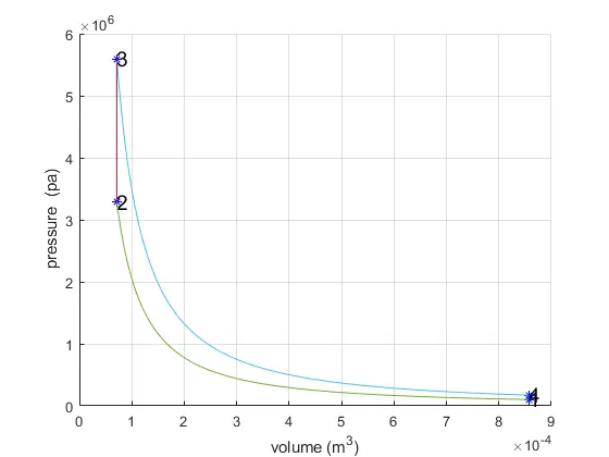
CYLINDER VOLUME - CRANK ANGLE
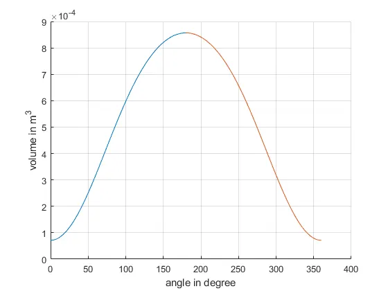
THERMAL EFFI. = 62.9893 %
6. CONCLUSION :
- as per graph(CYLINDER VOLUME - CRANK ANGLE) I can see that volume is increasing in shape of parabolic curve insted of linear curve(as per my assumption).
- as per thermal effi. equation, we can say, effi. will increasing by increasing the compression ratio.
- as per PV diagram I can see how the pressure will change at diff. stage of piston storke.
- so, from above calculations I am abale to compute all other diffrent cycles.
# ERROR WHILE CODING
- accidentally created one more parentheses in thermal efficiency equation
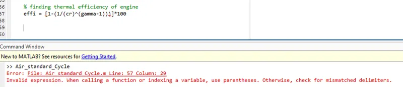
- getting a wrong plot
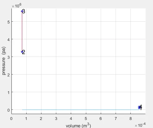
later, I have find-out, that I have put ' * ' instead of ' / '.