Working of Solenoid Block & Thermistor Block
1. AIM : Make a Simulink model using solenoid block & thermistor block.
2. OBJECTIVE OF THE PROJECT :
- Make a Simulink model of Doorbell using solenoid block with the following details:
-
When the switch is closed the electromagnet receives electrical power from the battery and pulls the metal arm to hit the bell & produce sound.
-
Create a situation where the switch is closed for 2 seconds and then released. Observe the physical movement of the plunger.
- Assume remaining parameters.
- Use a thermistor to sense the temperature of a heater & turn on or turn off the fan as per below conditions:
Temperature source: 20 °C for 0 to 10 seconds, 27 °C for 10 to 30 seconds, 23 °C for 30 to 50 seconds
Fan conditions: ON if the temperature above 25 °C, OFF otherwise.
3. BODY OF CONTENT :
- MAKE A SIMULINK MODEL OF DOORBELL USING SOLENOID BLOCK :
- Brief Introduction About Doorbell :
The electric doorbell/doorbell is a simple circuit that triggers a sound on the completion of circuit by pressing the button/switch. This works based on the electromagnetism principle. The image below shows the internal mechanism of an electric bell. The image contain Solenoid (Armature), Spring, Armature rod, Hammer and a Gong, etc. As an electric source, a battery can be used to power the electromagnet used in an electric bell. The electric circuit is completed by installing a push switch which you can press to generate sound in an electric bell. The switch also acts as the circuit breaker.
Here is Assuming that, while switch is on electricity is continually flowing throw circuits, "contact" is connected with the "softmetal" all time. There is only way to break the circuits by off the switch.
- Simulink Model Of Doorbell :
# INPUT :
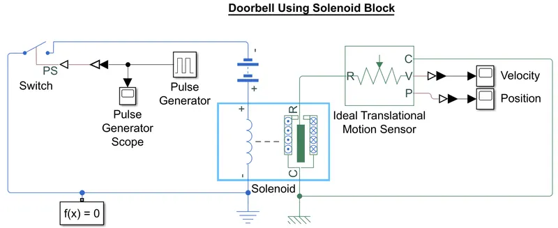
Above Block diagram represents the working of electrical Doorbell systems in a simulink environment. Let's understand each blocks and its working as below.
`=>` Pulse Generator Block :
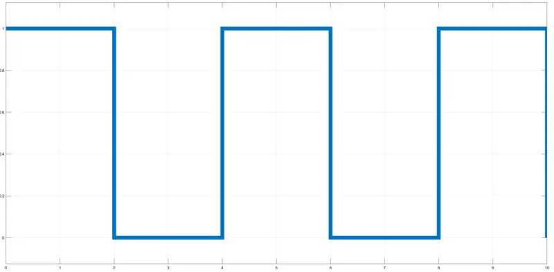
To Create a situation where the switch is closed for 2 seconds and then released, Here used Pulse generator block. As below image it's generated Physical signal for 2 sec on-off for 10 second stop time. where value 1 means "on" & 0 means "off". "Pulse Generator Scope block" used to visualize the "Pulse Generator block's" output.
`=>` Switch Block :
Here "Switch block" is Physical System. So it can't read the signal from the "Pulse generator block" directly, that's why here is the "Simulink-PS Converter block" used before the switch. A "switch block" controlled by a physical signal created by the "Pulse Generator block". If the external physical signal(PS) is greater than the threshold, then the switch is closed, otherwise the switch is open. So, here threshold value is 0.5. So on 1(PS) switch is ON & on 0(PS) switch is OFF.
`=>` Solenoid Block (as electrical characteristic) :
This block implements the electrical and mechanical characteristics of a solenoid. To get the position of the plunger in positive direction "port R moves away from port C" selected in 'Motion direction under excitation:'. And All others parameter putting in its defaults condition. Solenoid block has a maximum Rated voltage Vdc:50V and we are going to use a 12V battery.
`=>` Battery Block :
Now we are using "Battery Block" for constant power source & completing the electrical circuit. As default "Battery block" has 12V output with 2 Ohm resistance.
`=>` Solenoid Block (as mechanical characteristic) :
In "solenoid block" Mechanical translational conserving ports are given where, C associated with the case & R associated with the plunger. And putting all other parameters in default.
`=>` Ideal Translational Motion Sensor Block :
Using this block we measuring the velocity & displacement of plunger. The physical signal ports V and P report the velocity and position, respectively, of port R relative to port C. Usina "scope block" visualizing the velocity & displacement shown in output. Here Scope can't read signal/value directly that's why "PS-Simulink Converter block" is used.
`=>` Solver Configuration Block and Reference Block :
Lastly, Attaching "Solver Configuration Block". Each physical network represented by a connected Simscape block diagram requires solver settings information for simulation. The Solver Configuration block specifies the solver parameters that the model needs before beginning the simulation.
And then for the electrical system used "Electrical reference block" & for Mechanical system used "Mechanical Translational Reference Block".
# OUTPUT :
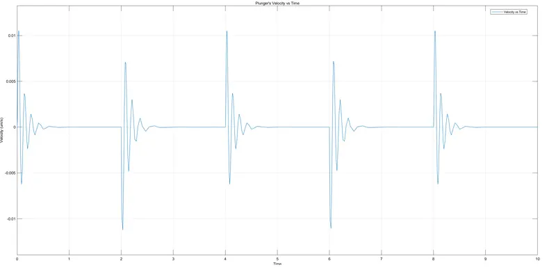
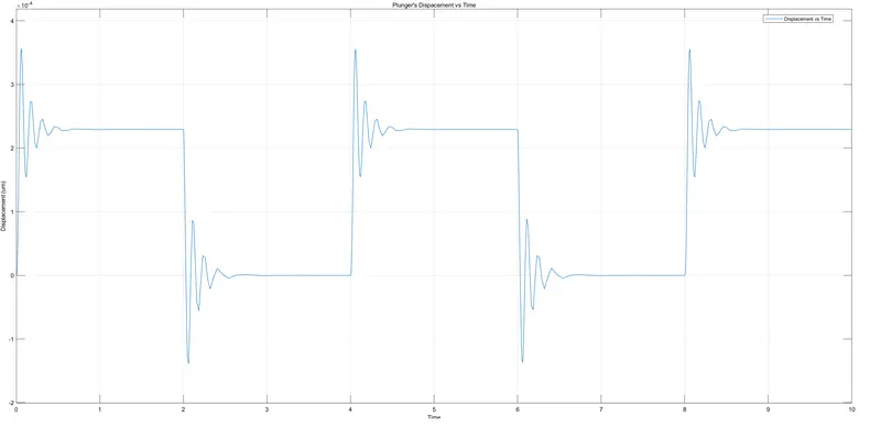
Below is showing the output of Plunger velocity & displacement respectively.
- USE A THERMISTOR TO SENSE THE TEMPERATURE OF A HEATER & TURN ON OR TURN OFF THE FAN:
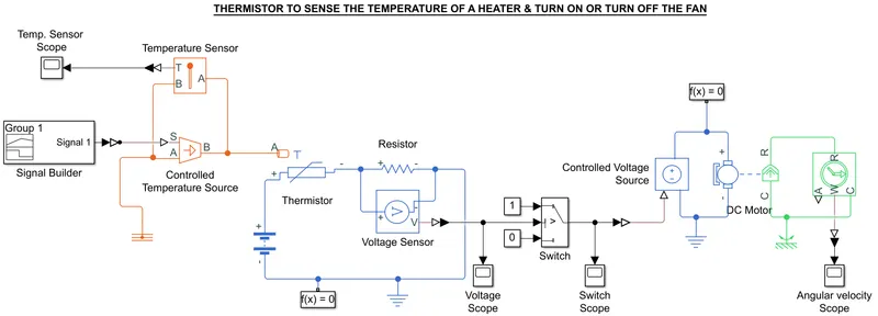
Above Block diagram represents a working Thermistor to sense the temperature of a heater & turn on or off the fan in a simulink environment. Let's understand each blocks and its working as below.
`=>` Signal Builder Block :
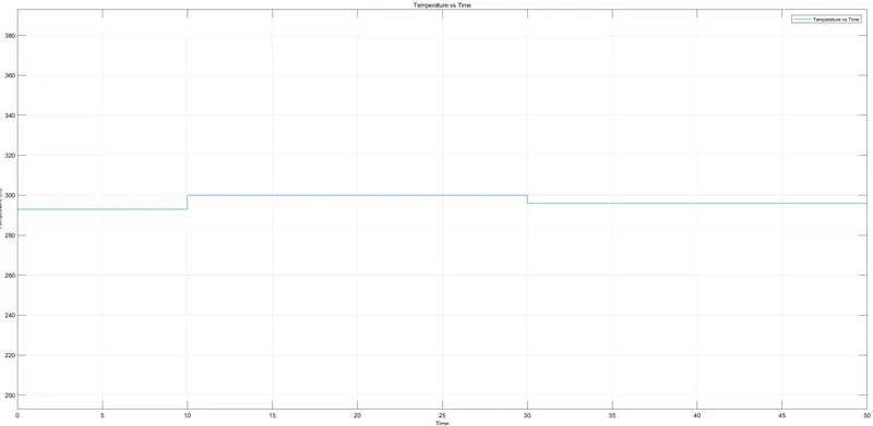
As per condition Temperature source will be 20 °C for 0 to 10 seconds, 27 °C for 10 to 30 seconds and 23 °C for 30 to 50 seconds. So, First we have to build Physical signals(PS) according to temperature source with respect to time. Here temperature is in Celcius & simulink thermal library default SI unit is K. So converting 20,27,23 into Kelvin 293,300,296 respectively. Now, projecting points on X-axis 0,10,30,50 and on Y-axis 293,293,300,296 in this block.
`=>` Controlled Temperature Source Block :
This is an ideal energy source in a thermal network. Port S is a physical signal port, through which the control signal that drives the source is applied. Here the "Controlled Temperature Source Block" is Physical system so it can't read signals directly from the "Signal Builder Block". So using a "Simulink-PS Converter Block" it can read.
Normally "Thermal Reference Block" attached to the "A port" of this block to generate a difference between "B & A port". Where at "Thermal Reference Block" the temperature is equal to absolute zero.
`=>` Temperature Sensor Block :
Now, To check that "Controlled Temperature Source Block" gives the right output or not, here "Temperature Sensor Block" is used. That measures the temperature in the thermal system. Using a "PS-Simulink Converter Block" & "Scope Block" can be seen as below.
`=>` Thermistor Block :
A thermistor is a thermally sensitive resistor that exhibits a precise and predictable change in resistance proportional to small changes in body/system temperature. This block represents an NTC thermistor using the B-parameter equation. Heat flow of temperature from "Controlled Temperature Source Block's port B" received by "Thermistor Block's 'port A'. And using that value create a voltage difference in the electrical system.
`=>` Electrical System :
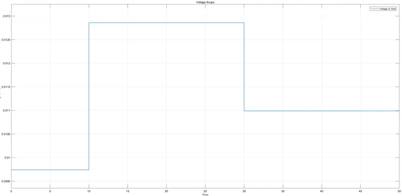
Now, Attach the "Battery Block", "Resistor Block", "Voltage sensor Block" & "Electrical Reference Block". Here is Battery block and Resistor block in its default condition. Using a "Voltage sensor Block" we measur the voltage of the resistor. Using "PS-Simulink Converter Block" & "scope block" we can see voltage difference as per below.
`=>` Switch Block :
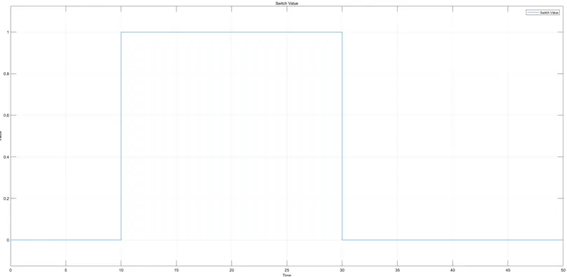
This is Combine multiple signals into a single signal type switch block. There is one 'Control input signal port' & 'two inputs". Based on 'Control input signal' either the first or second data input to the output. As per above 'Voltage sensor' result 25deg comes to 0.0119mV. SO, set threshold value at 0.0119. And as two inputs one of is 0 & one of is 1. where 0 & 1 represent off & on respectively.
Here Criteria for passing first input is 'u2>Threshold'. So, based on "Switch block" we can see the result as below.
`=>` DC motor Assembly :
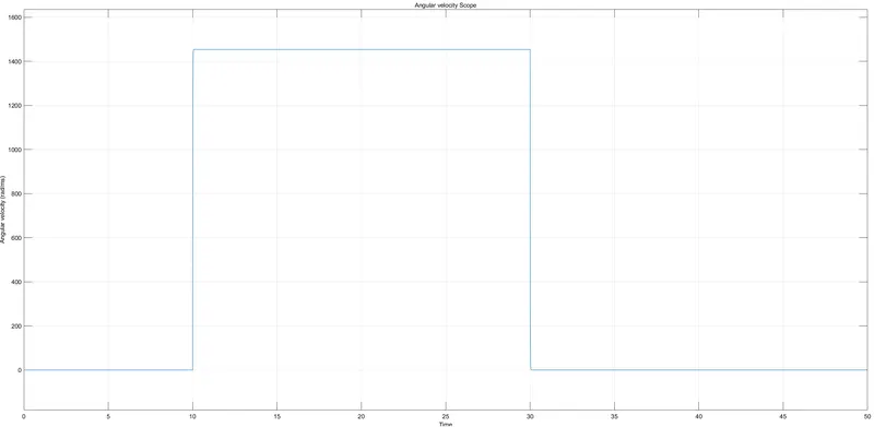
Based on the above graph, we can see that 10 to 30 sec temp is higher than 25 . So that way output is 1 means fan is on.
Here fans are represented by a "DC motor block" with the other block arrangements. As output of fan spindle we can see the angular velocity of the motor as below.
4. CONCLUSION :
From the above Exercise I learned how I can perform a Simulink Block diagram of a Actual physical system with some limitations & assumptions. How can be output generate and read them.
REFERENCES :