Wiring harness design in CATIA V5 - 3D modeling Week 5 & 6 Challenge
Aim: To Create as routing harness assembly between th connnectors using Electrical harness workbench in Catia V5.
Objectives:
- To create the route the harness layout using Electrical workbench in Catia V5 with given set of connnectors.
- To add the protective covering over the branches.
- To add annotations to the connnectors.
- To connected the different harness assembly with each other.
Harness Layout:
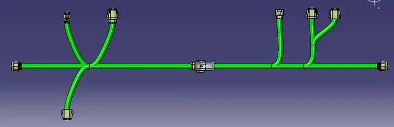
The below harness routing image is provided and we have to follow it and create the electrical harness assembly according to that and positions also.
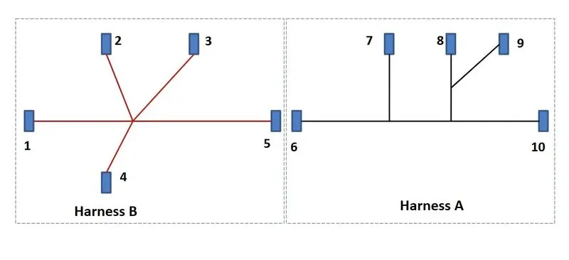
List of Connectors:
- Connector 1
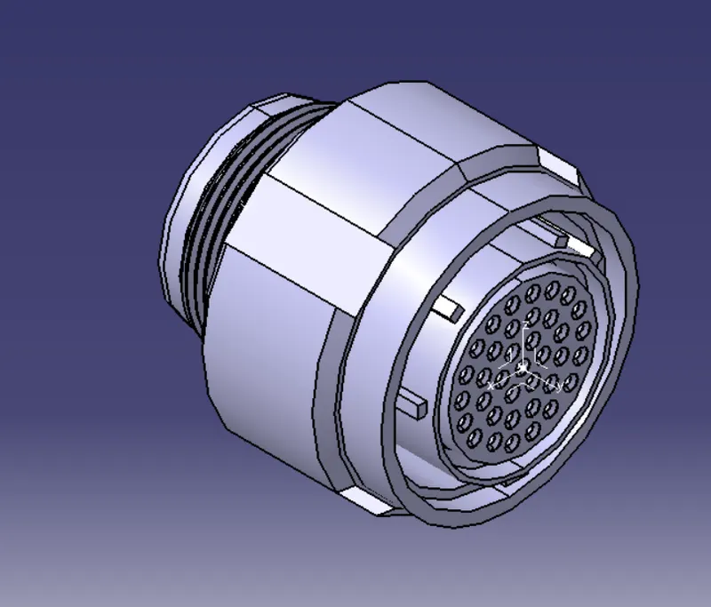
The file is opened in the Part design workbench. Now the point on the either side of the connector is created by selection between points as shown below.
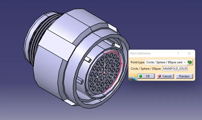
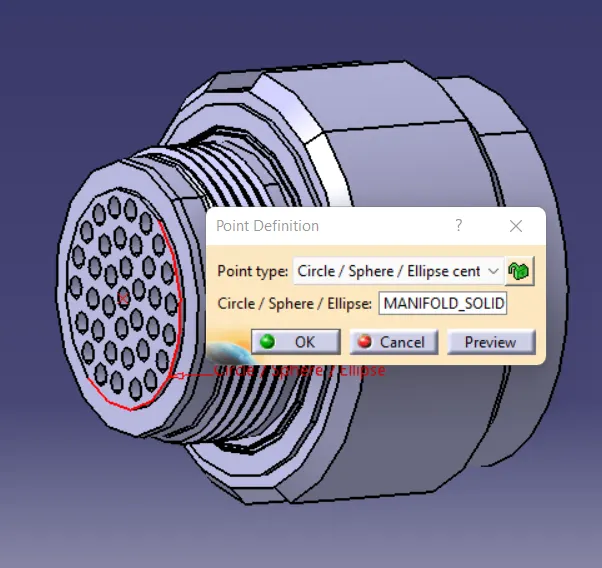
The axis is created as shown in below figure.
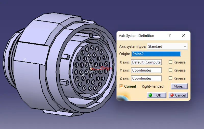
Now the model is transferred to electrical part design. The model is designed as connector. Now the one end point of the connector is defined with a bundle connection point.
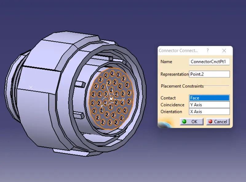
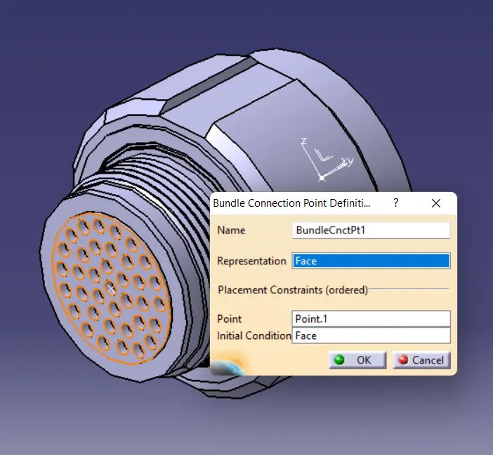
Now save the file.
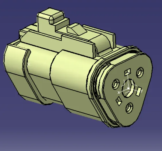
Same procedure is followed to the other connectors.
- Connector 2
- Connector 3
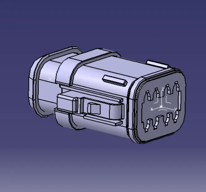
- Connector 4
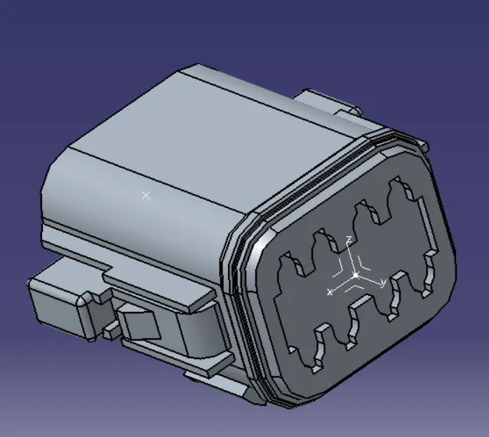
- Connector 5
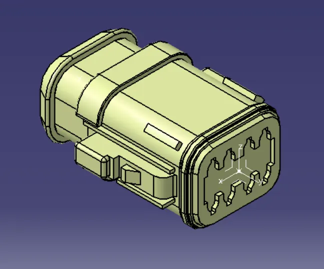
- Connector 6
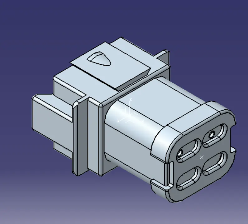
- Connector 7
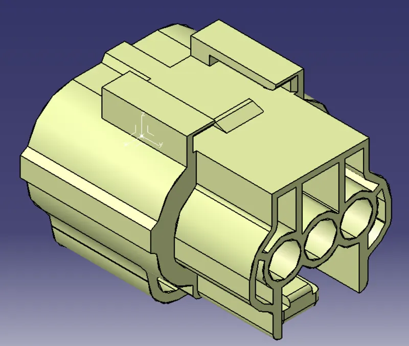
- Connector 8
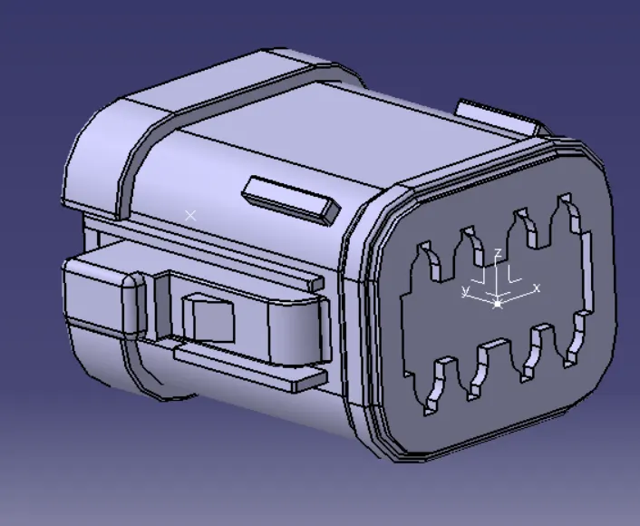
- Connector 9
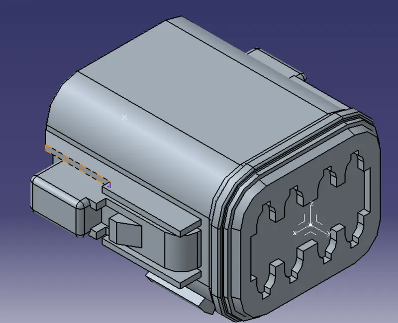
- Connector 10
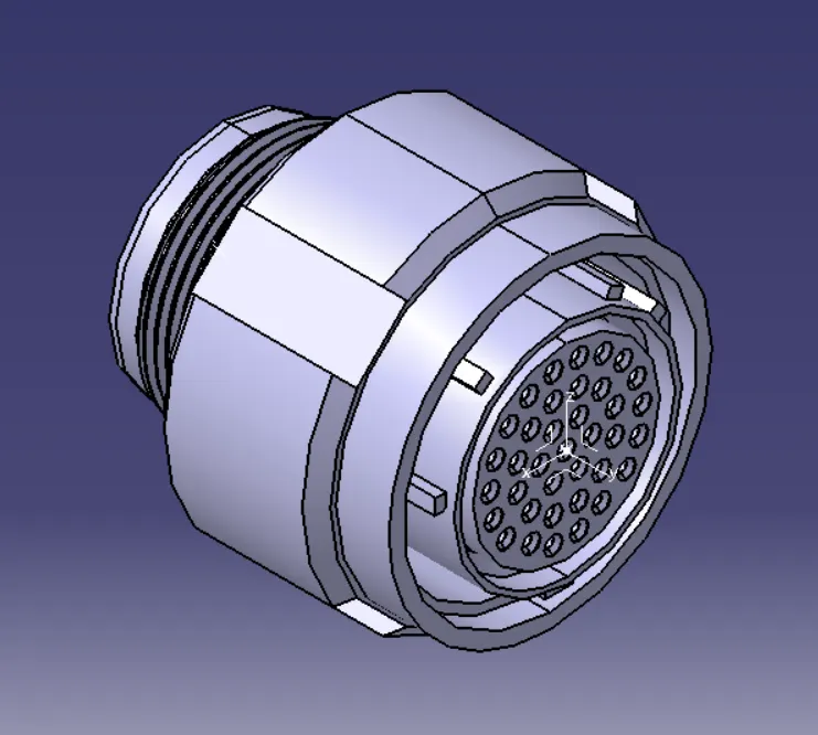
Next step is to create the Harness A and Harness B as per the given routing image.
Electrical Harness Routing:
- Harness A
All the connector (such as connnector 1,2,3,4,5) are imported and arranged as per the harness image using snap, manipulate and smart move command.
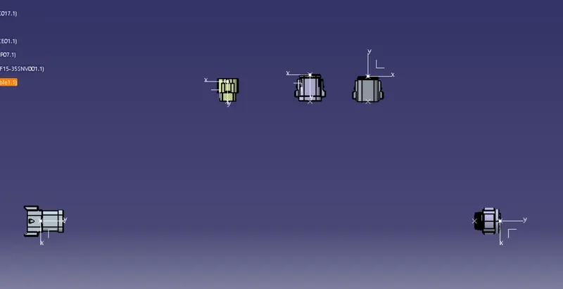
Now the workbench is changed to Electrical Harness Installation. Before moving on to create the bundle branches the product is selected and the geometrical bundle option  .
.
Now we create a bundle between the connectors as shown below.
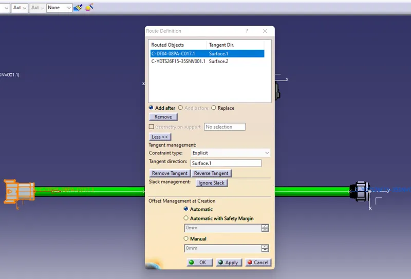
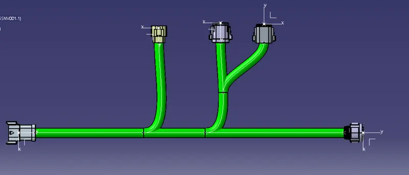
Here the assumed branch diameter selected is 15cm just for reference. Now all the branches are created with the help of split branch at particular point as per the harness drawing as shown below.
Harness B:
All the connector (such as connnector 6,7,8,9,10) are imported and arranged as per the harness image using snap, manipulate and smart move command.
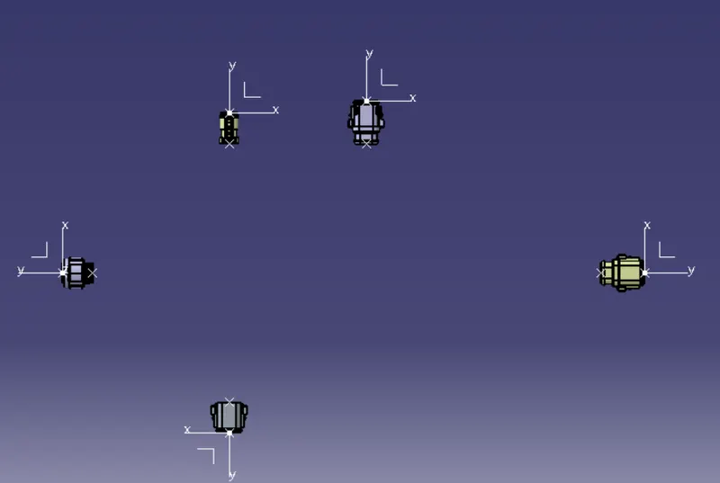
Now the workbench is changed to Electrical Harness Installation. Before moving on to create the bundle branches the product is selected and the geometrical bundle option .
Now we create a bundle between the connectors as shown below.
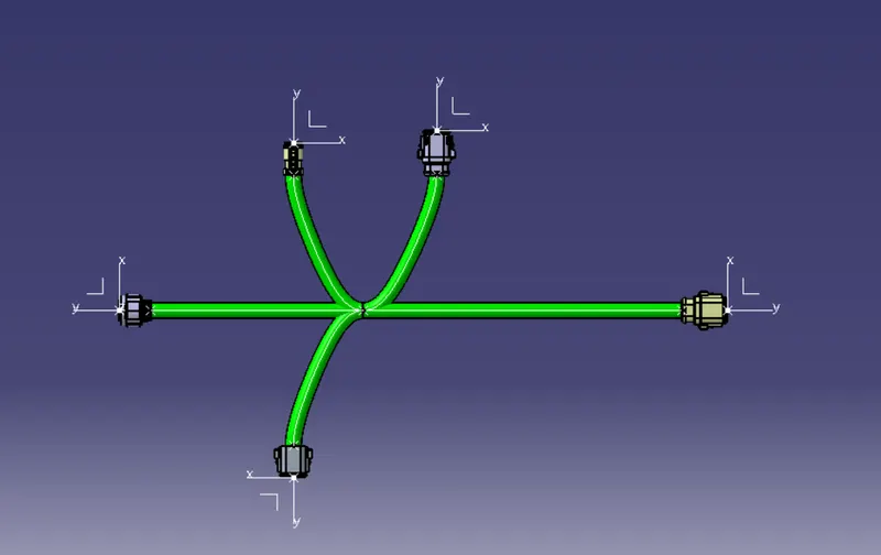
Now save both the files.
Next step is to check the bundle continuity in both the harness A and B.
This can be done by going to Edit > Search. Now a new popup appears as shown below.
In advanced tab select the following options:
Workbench = Electrical
Type = Bundle Segment
Attribute = Fully connected.
Select option true in the next window and click preview. The list of all the connected bundle segments are listed and indicates that the bundle branches are fully connnected.
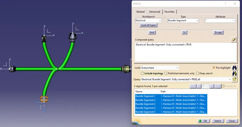
Similary for the other harness assemble the connections are checked.
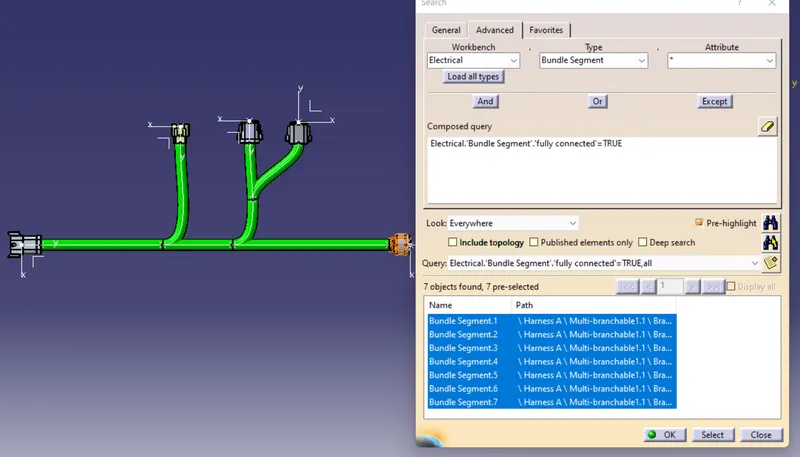
Next step is to interconnect both the harness A and B.
The workbench should be shifted to electrical assemble design. Now the new workbench is opended. Select Connect Electrical deivces option  . Select the end connectors of both the harness to be connected with each other.
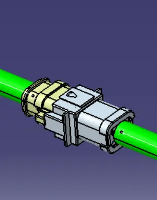
Checking Bundle harness Warnings:
The geometrical warnings are shown for the bend radius, position and diameter of the bundle.
So now, if there is any error in the input values or entries the branch route will reflect red colour and the respective bundle inon in the feature tree will be reflecting a yellow colour as shown beelow.
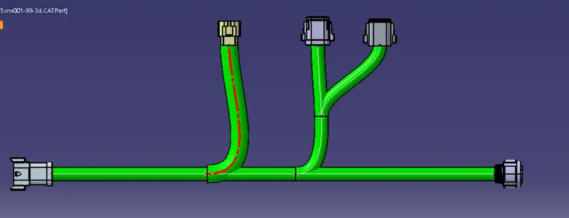
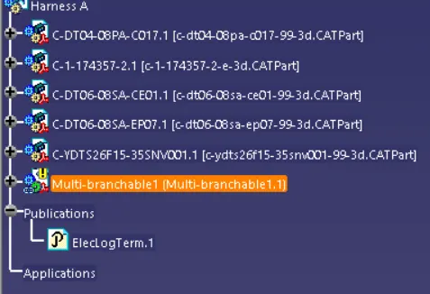
We have to be careful with the entered values and also ensuring that the direction of the point or the diamter are proper. In the above figure the warning was because of the diameter value was large. This error can be resolved by reducing the diameter.
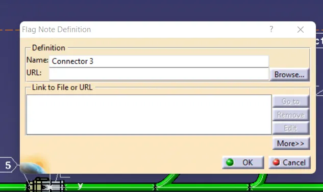
The last procedure is to give annotations to all the connectors as per the routing diagram provided.
The workbench is shifted to Mechanical assemble design. Now the Flag  is clicked and then the particular connector is clicked and then the name of that connector is written and click ok. In a same way all the connectors are given a annotations as below.
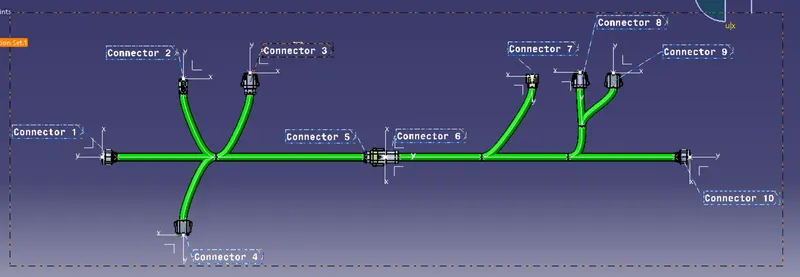
Finally the files has to converted to CATPart file using the below steps
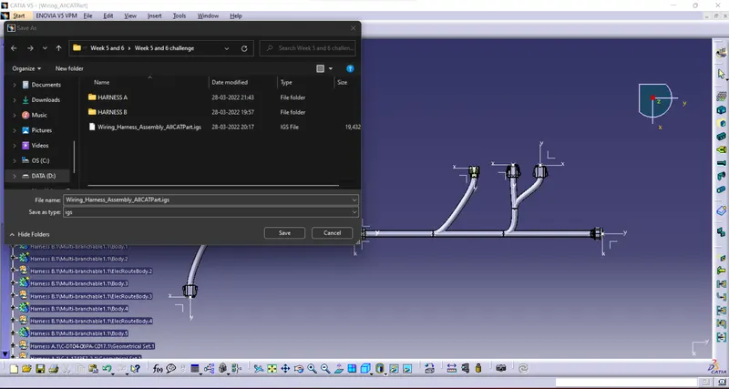
Tools > Generate CATPart file > Enter the Name of the file > OK.
The CATPart file is now created. Now open the file. Click on save as and save as .igs file
Conclusion:
- The Wiring harness routing as per the harness image provided is created.
- Both the harness are checked for bundle segment warning.
- The harness assemblies are interconnected with each other.
- Annotation are added to the repective connectors.
- CATPart file is generated and then converted to .igs file
Thank you.