Wiring harness routing & packaging Rules Week 3 Challenge
Assignment 2
P-camp >
Download P clamp file form TE.com
I. Then define its geometrical properties by hiding rubber shell over p clamp
II. Take a point from point definition and from circle defined take same by other side also
III. Now go to plane definition and take a plane through point reference as parallel surface of clamp.
IV. Do same with other side also .
V. Then take third plane parallel to bottom at a distance of 2mm from bottom plane .
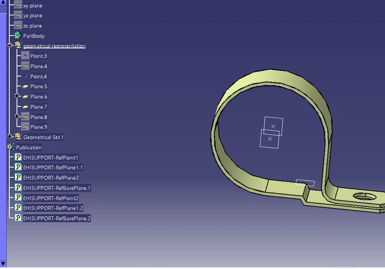
Define its electrical properties.
VI. Now go to electrical part design to define its electrical properties
VII. Go to support parts and then select first point first plane then second point and second plane .then base plane .
VIII. Go to support part again and select second point second plane but here unable to select first plane again because was selected previously and then select base plane.

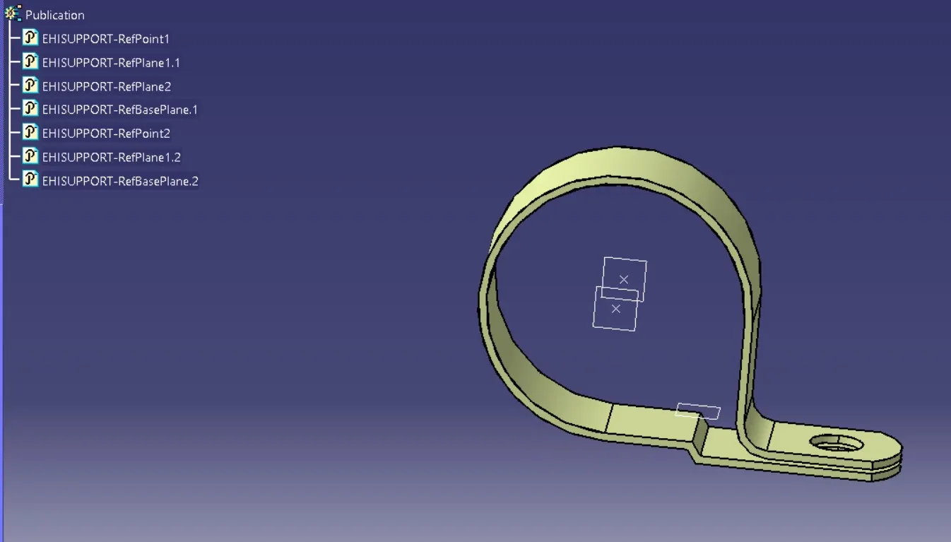
Define electrically to Back Shell
IX. Download part 1738312 from T.E com
X. Now extract zip file and open this part in catia application
XI. Now go to point definition there is between option select that and select two corner points of mating surface and mid point of this part and select co-ordinate system and take a point as mid point Y axis towards face,X axis towards locking direction and Y axis upside.
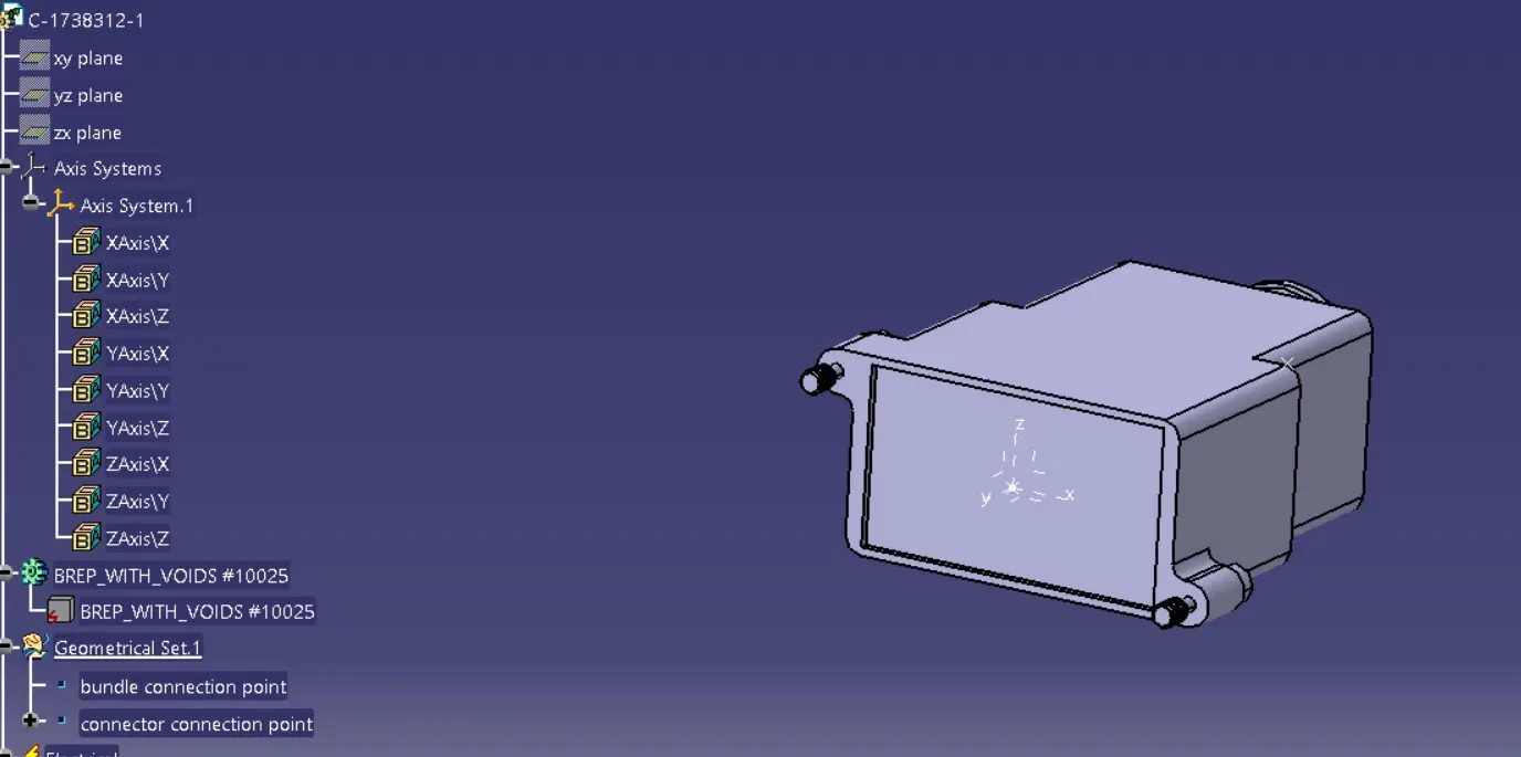
XII. Then select point definition again and select circle/ellipse/arc option and select circle of back shell from other side then take a point there.
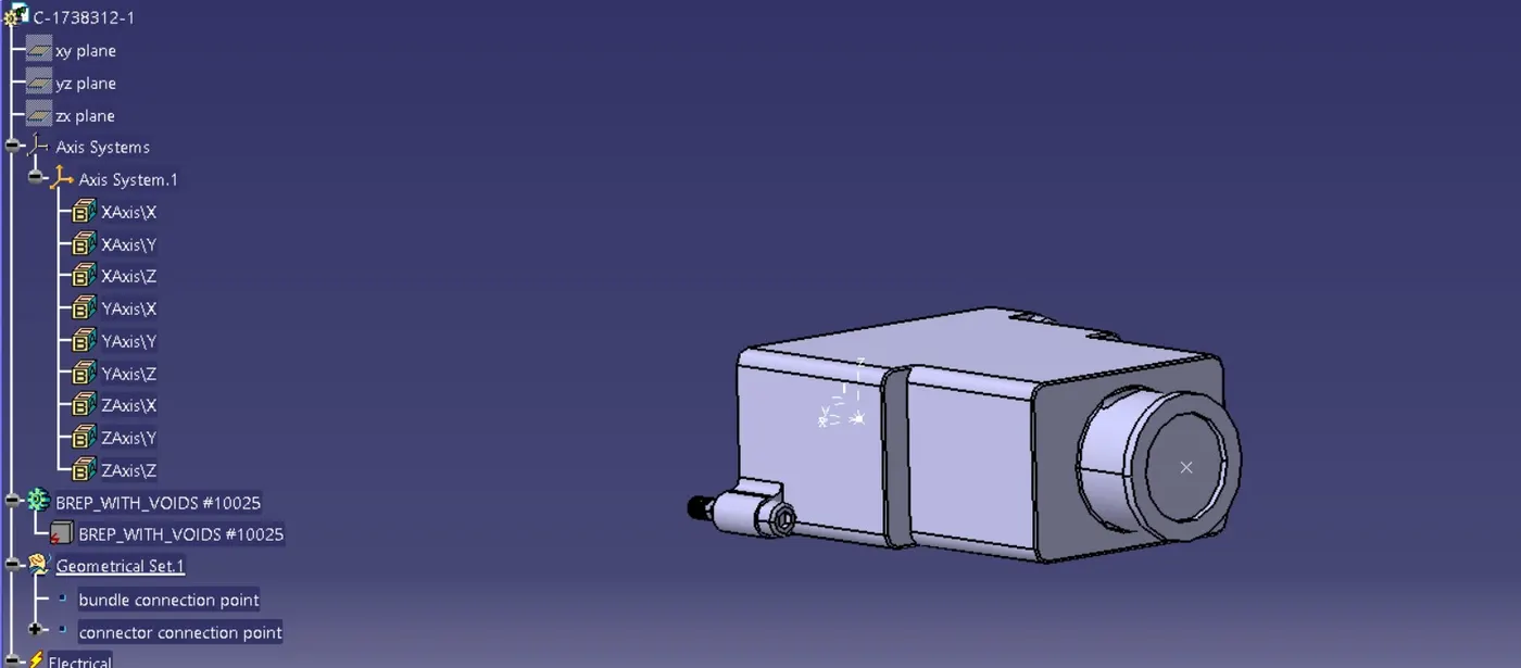
XIII. Define this back shell electrically
XIV. Go to electrical part design then select define back shell option from side bar and select part.
XV. Then there is option of back shell definition and part number keep this as it is and below that there is extra length kept this as it because we don’t need extra length right now.
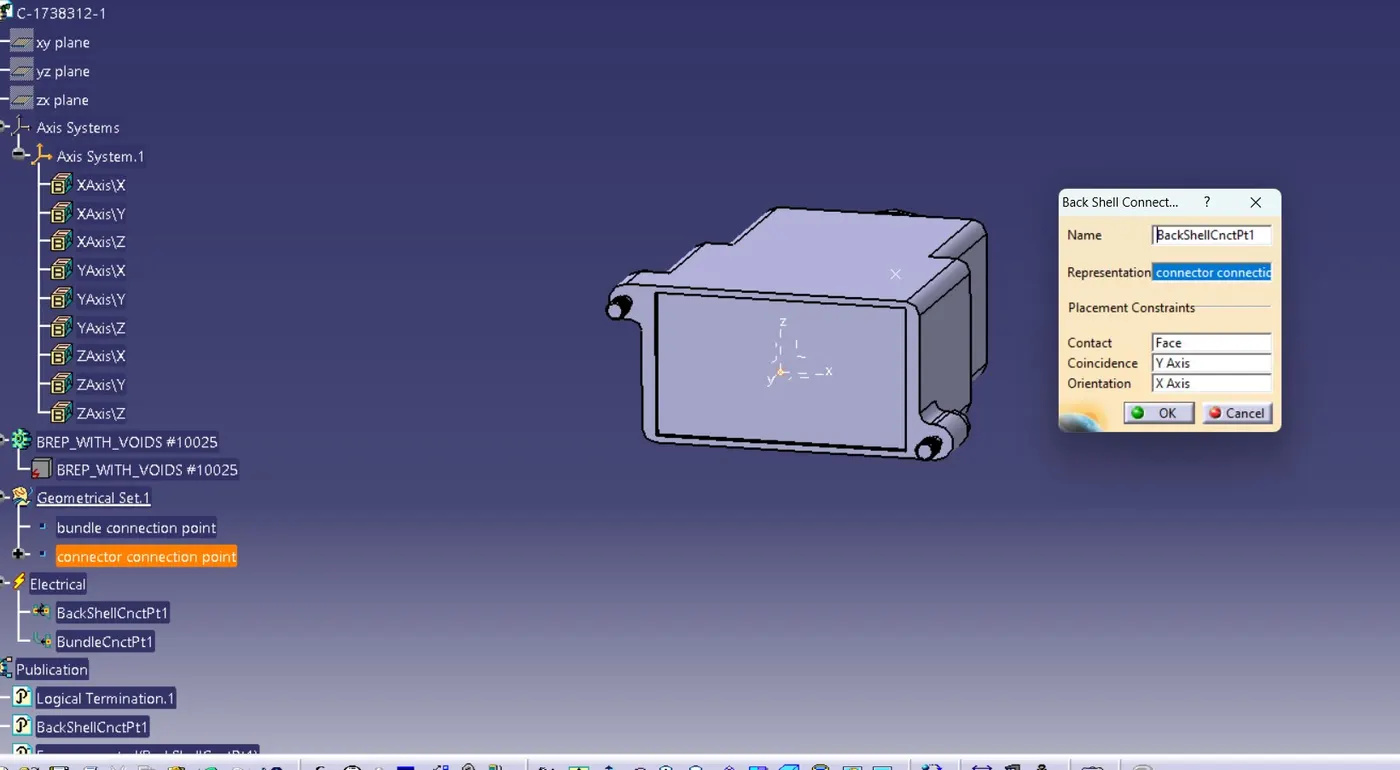
XVI. Then go to Back Shell connection point and Representation connector connection point contact face and coincidence y axis and orientation z axis .
XVII. Now define bundle connection point by taking last face point and representation face point bundle connection point and initial face is normal face.
 define it as back shell electrical part
 back shell connection point
COT TUBE CREATION
XVIII. Cot tube not available to any site .
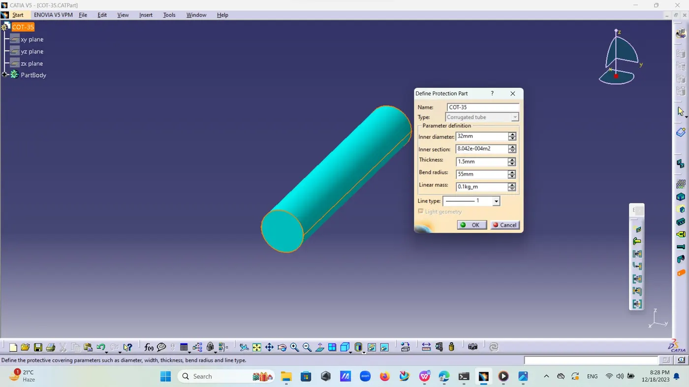
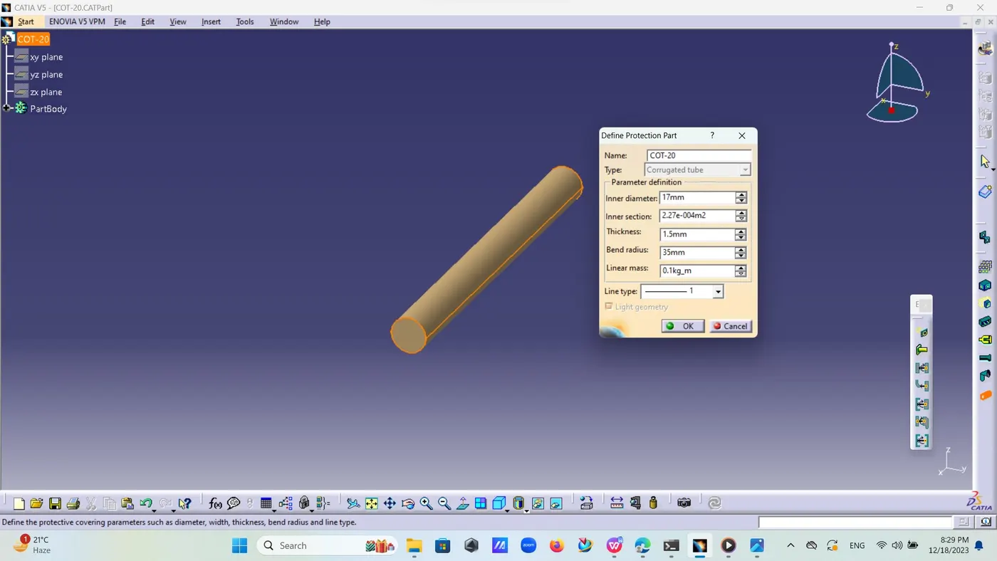
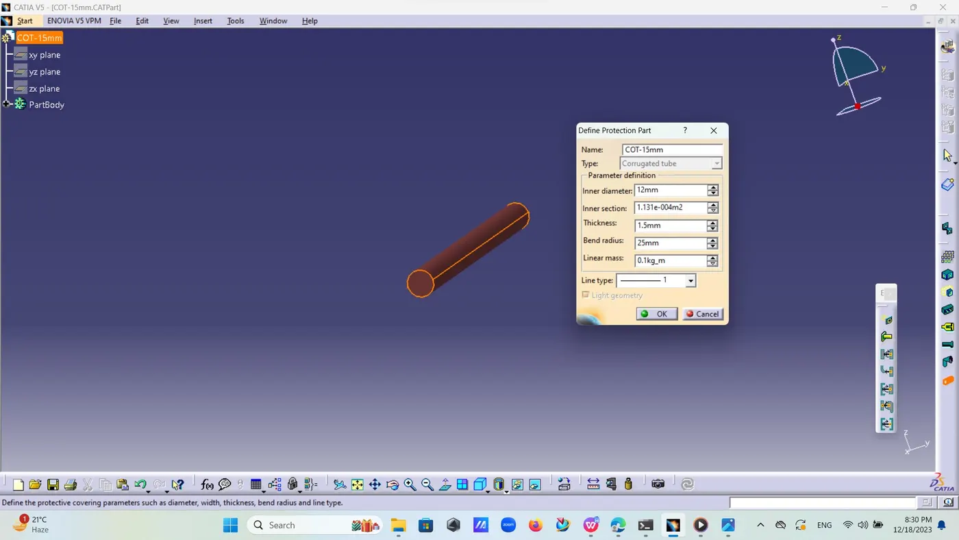
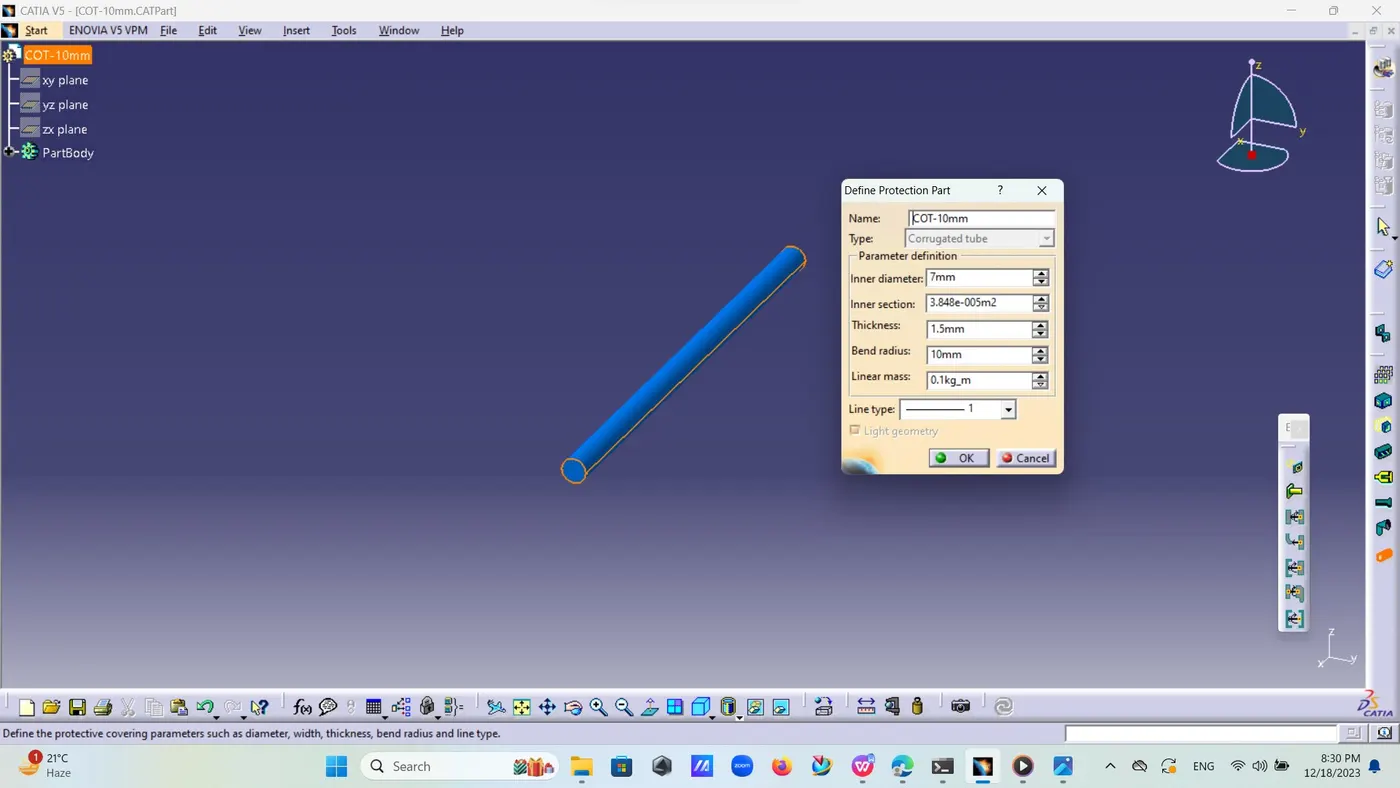
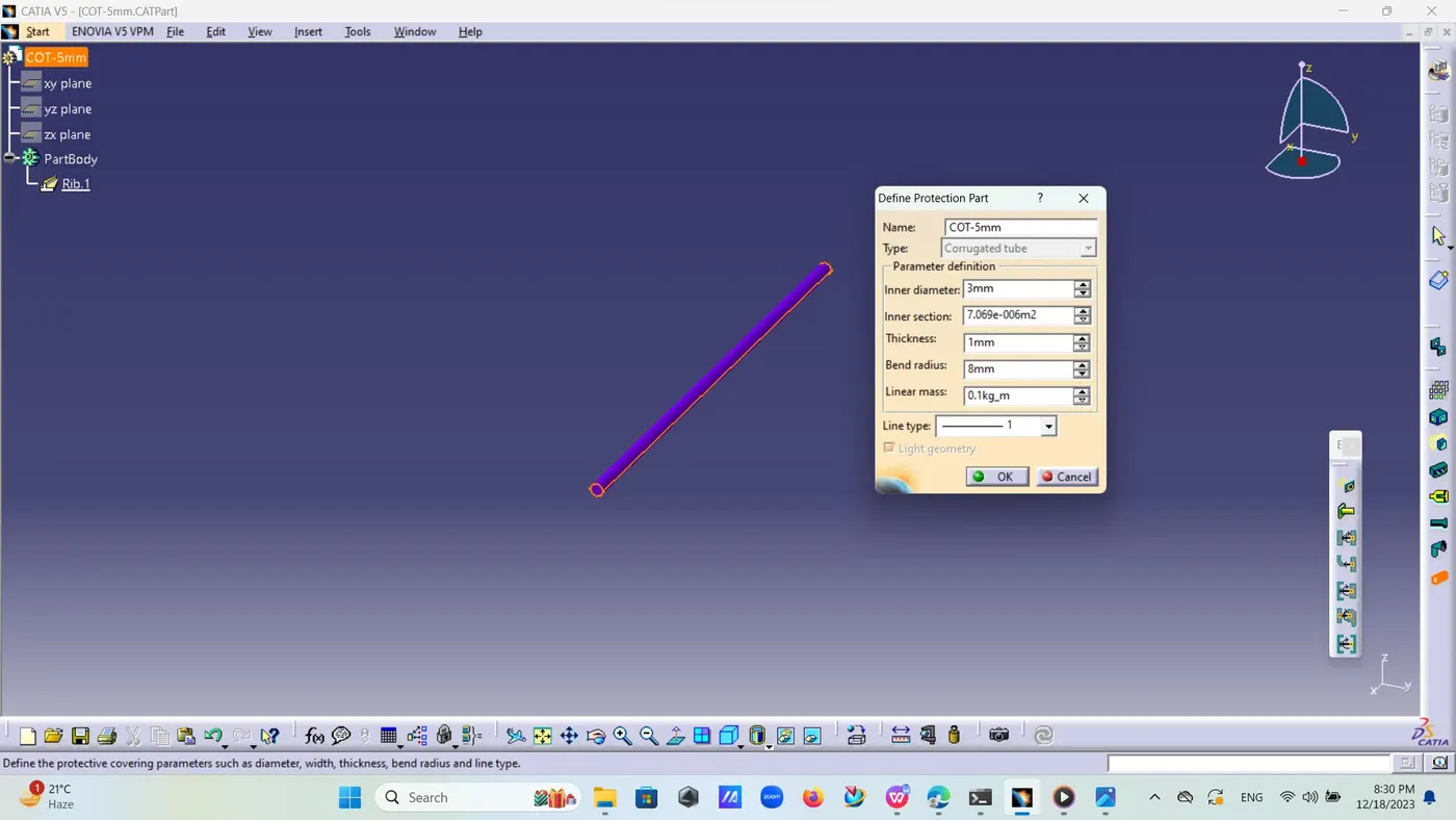
XIX. Take a new part then electrical part design then there create new part by the name of cot tube size because size is its identity .ex COT-20mm.
XX. Then go electrical part design and select select define protection part and then select part 20mm and define its inner diameter thickness and bend radius its bend radius is 1.5 times of external diameter normally depending upon its flexibility.
XXI. If cot tube is more flexible then its bend radius is less and if bend radius is more then if it is rigid.
XXII. Create catalogue for cot tube.
XXIII. Go to file -create catalogue document name is as Slit COT there is sub option of type of catalogue call it conduit .
XXIV. Now there is book type symbol open it and select add family there is sub type of slit cot select made part and save it to catalogue .
XXV. Add all the Cot tube to that catalogue one by one.