Wiring harness routing & packaging Rules Week 3 Challenge
WIRING HARNESS ROUTING AND PACKAGING
Wiring harness routing and packaging refer to the process of designing, organizing, and securing electrical wiring systems within a vehicle, machinery, or any complex system that requires interconnected electrical components. Proper routing and packaging of wiring harnesses are essential to ensure the safety, reliability, and efficient operation of the electrical system.
Here are some key aspects involved in wiring harness routing and packaging:
DESIGN AND LAYOUT: The first step is to create a detailed design and layout of the electrical system. This includes identifying all the electrical components that need to be connected, determining their locations, and planning the path the wires will take between them.
WIRE SELECTION: Choosing the right type and gauge of wires is crucial for the specific application and the current they will carry. It's essential to consider factors such as voltage levels, temperature resistance, and environmental conditions.
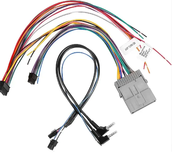
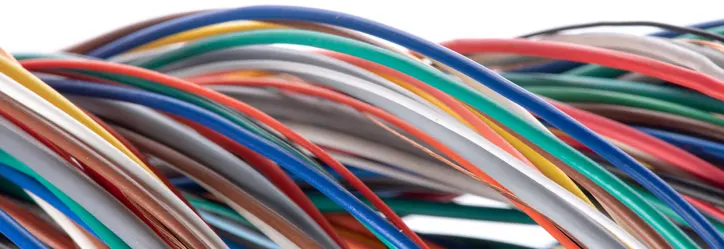
WIRE PROTECTION: To safeguard the wires from abrasion, heat, moisture, and other potential hazards, various protective measures are used. These may include wire loom, convoluted tubing, heat shrink tubing, and braided sleeves.
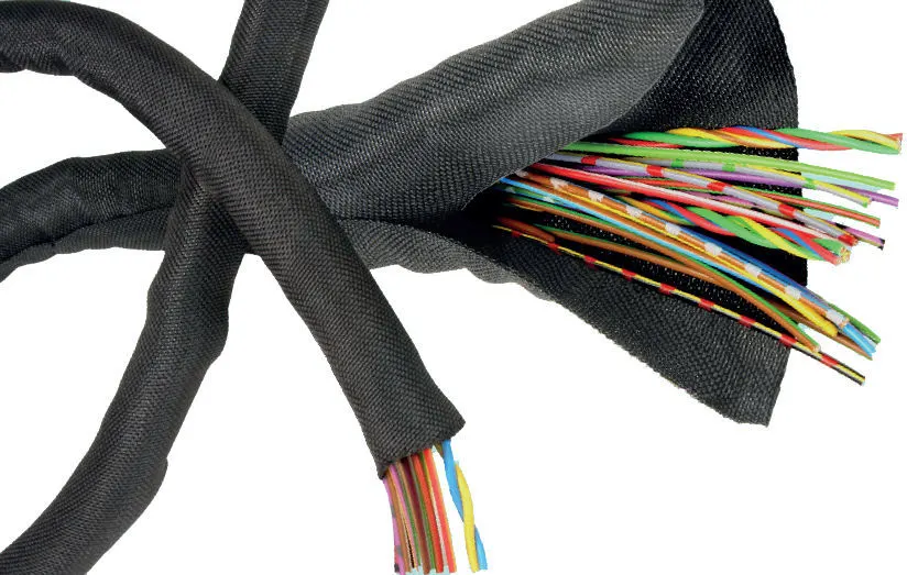
ROUTING CHANNELS: Wiring harnesses are usually routed through dedicated channels or paths within the vehicle or equipment's structure. These channels keep the wires organized, prevent tangling, and reduce the risk of damage due to friction or vibration.
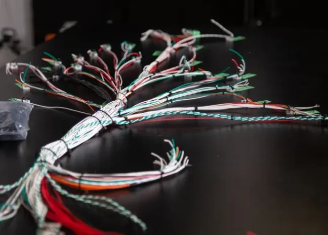
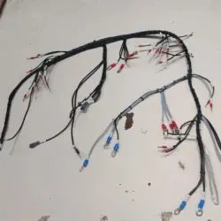
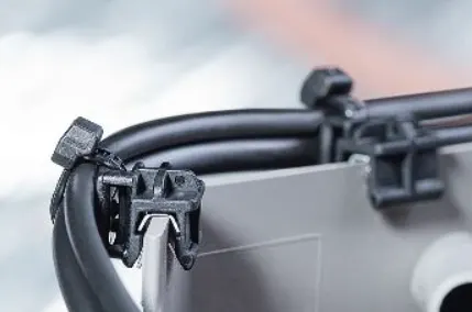
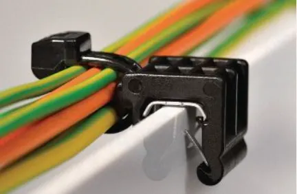
RETAINING CLIPS AND TIES: Wiring harnesses are held in place using clips, ties, or clamps. These secure the harness and prevent it from moving excessively, which could lead to wear and potential short circuits.
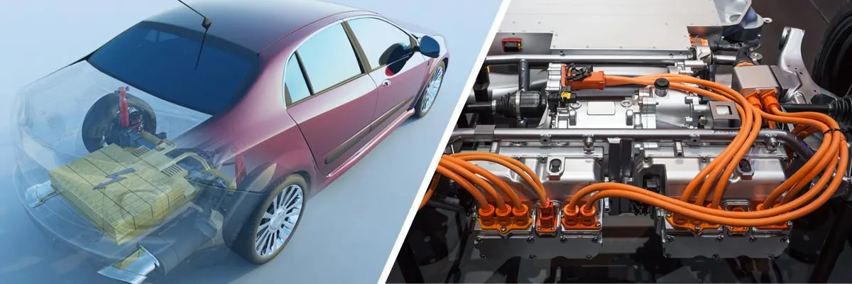
SEPARATION OF POWER AND SIGNAL WIRES: High-power wires carrying currents for various systems should be separated from low-power signal wires to avoid interference and maintain signal integrity.
SERVICEABILITY AND REPAIR: Proper packaging allows for easier access to individual wires and components, making maintenance, troubleshooting, and repairs more manageable.
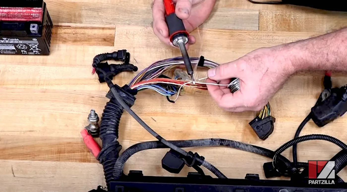
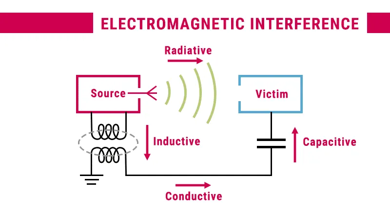
ELECTROMAGNETIC INTERFERENCE (EMI) CONSIDERATIONS: In applications where electromagnetic interference may be a concern (e.g., in automotive or aerospace industries), special shielding or twisted-pair wiring may be used to reduce interference.
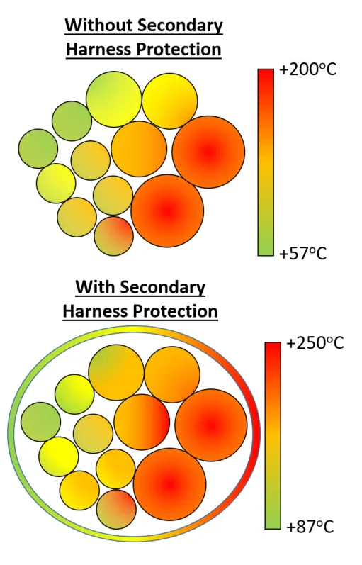
THERMAL CONSIDERATIONS:Wires carrying high currents or located near heat sources should be properly insulated or routed to handle the heat generated.
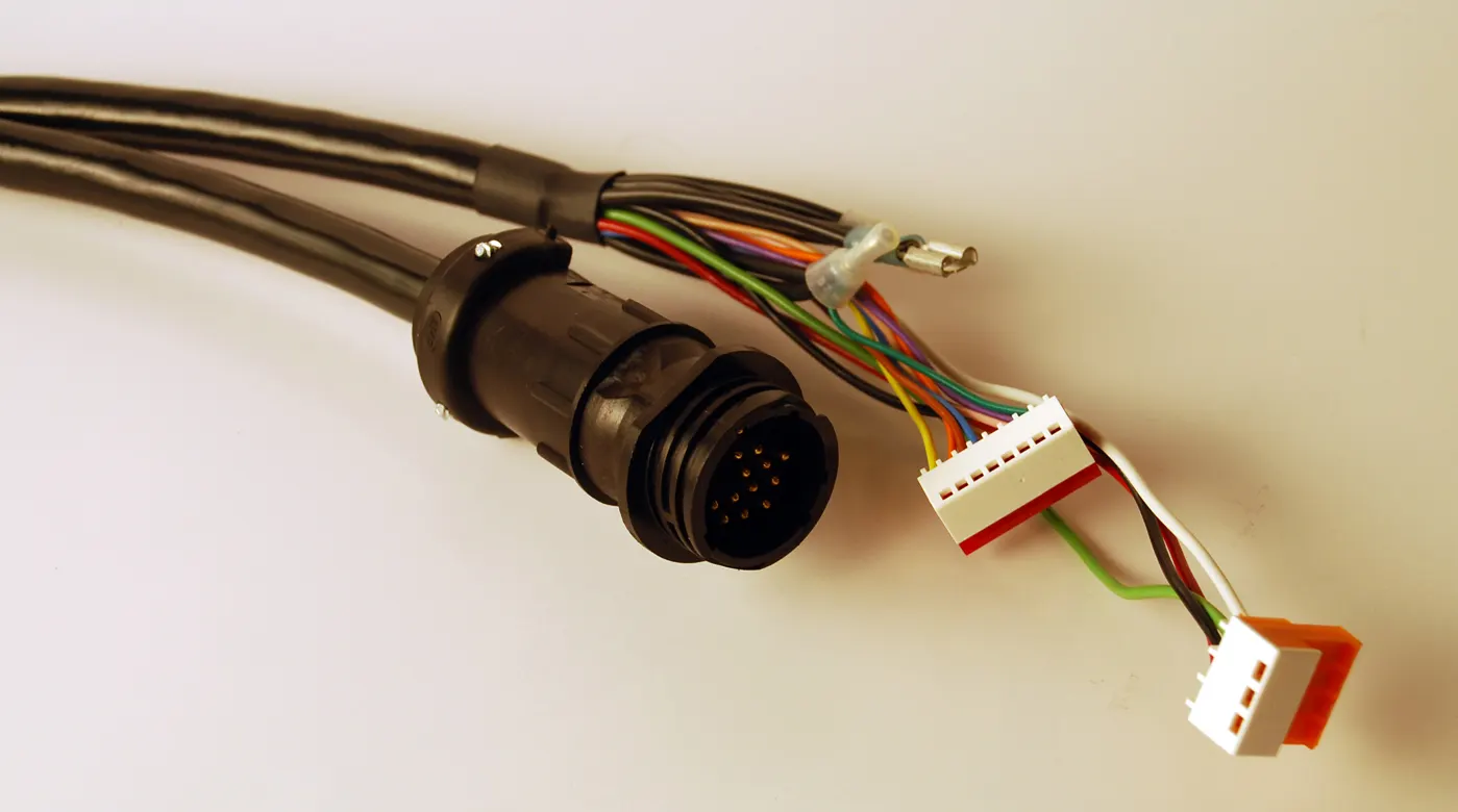
COMPLIANCE WITH STANDARDS: Wiring harness routing and packaging should adhere to relevant industry standards and regulations to ensure safety and compatibility.
The process of wiring harness routing and packaging requires careful planning and attention to detail. Computer-aided design (CAD) software and simulations are often used to optimize the layout and assess potential issues before physical implementation. Additionally, thorough testing and quality control are crucial to validate the integrity of the wiring harness before it is put into service.
QUESTION NO - 1
Download following cad data & define it as Electrical support using Electrical Part design Workbench. Define all the necessary properties.
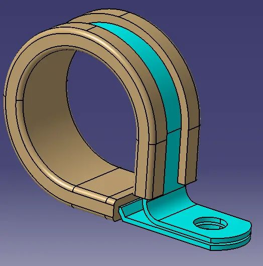
ANSWER
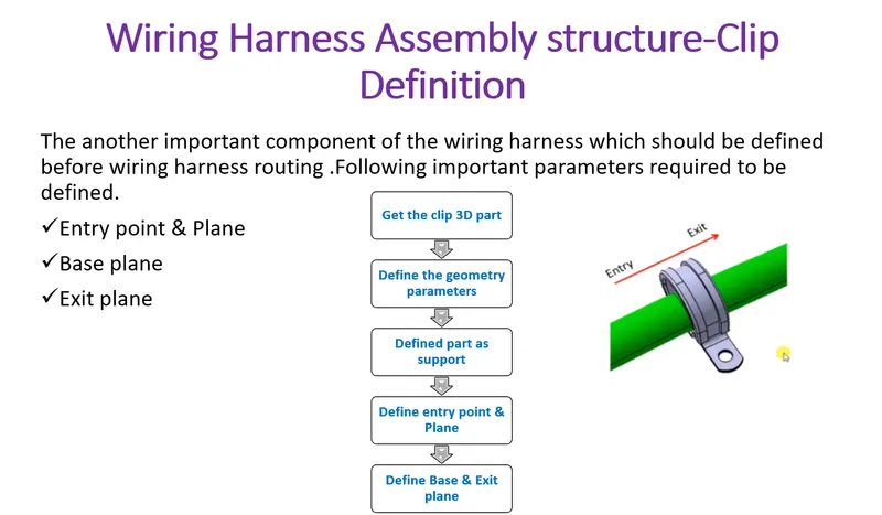
Steps to define define it as Electrical support using Electrical Part design Workbench,
1.First create a point by using circle center on the two sides of the clamp.
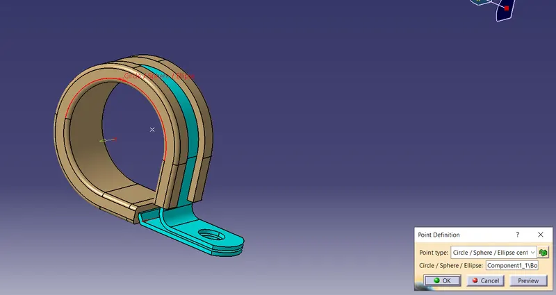
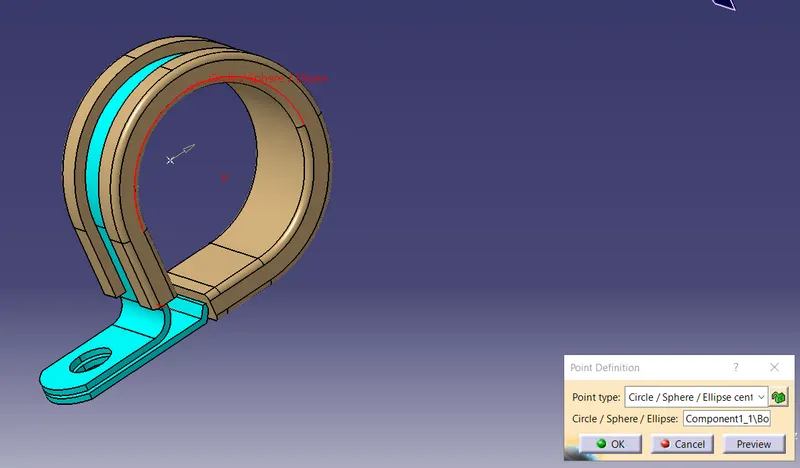
2.Then create a plane on the entry point, exit plane and in the base of the clamp.
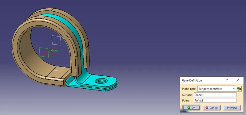
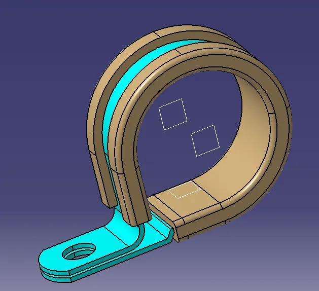
3.Then switch to electrical part design.
4.Click on support defination - select part - select entry point - select entry plane, exit and base plane.
5.Again Click on support defination - select part - select exit point - select exit plane and base plane as secondary plane is automatically taken.
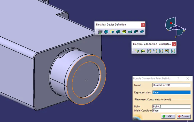
Q2. Download following Back shell cad data & define it as Electrical back shell using Electrical Part design Workbench. Define all the necessary properties.
Steps to define define it as Electrical support using Electrical Part design Workbench,
1.create Back shell entry point.
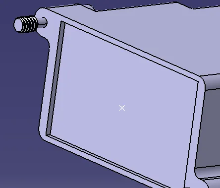
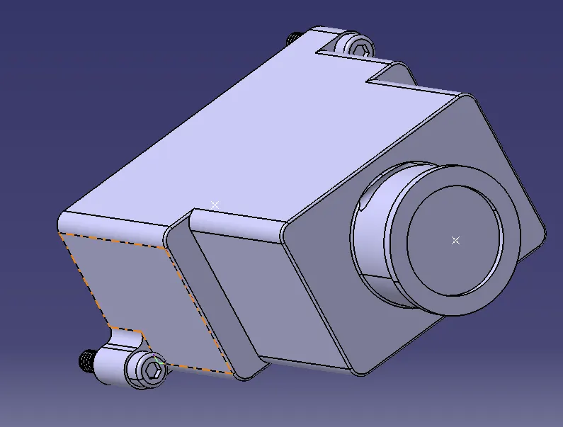
2.create axis system for back shell entry.
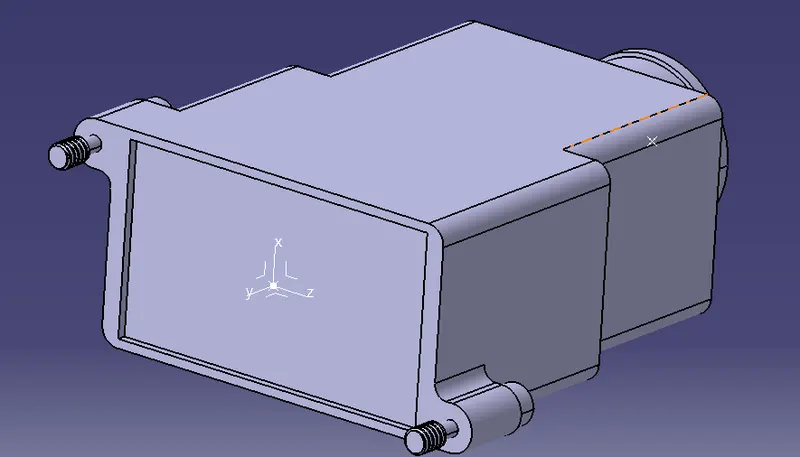
3.create bundle connection point.
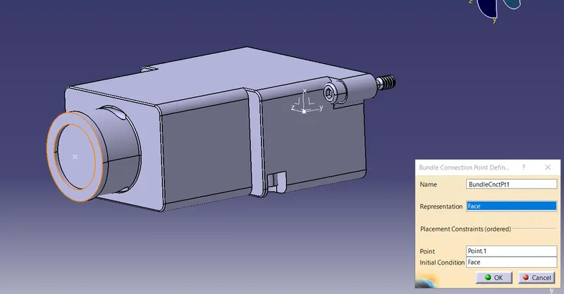
4.Define part electricaly as back shell.
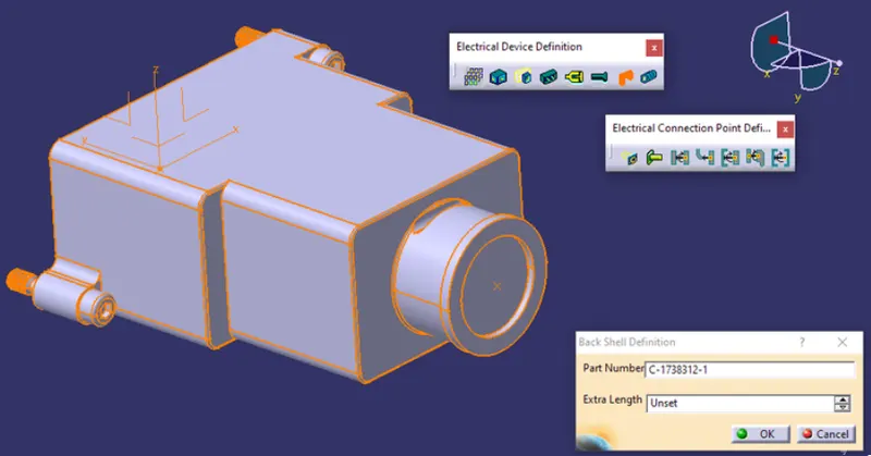
5.Then define Back shell connection point.
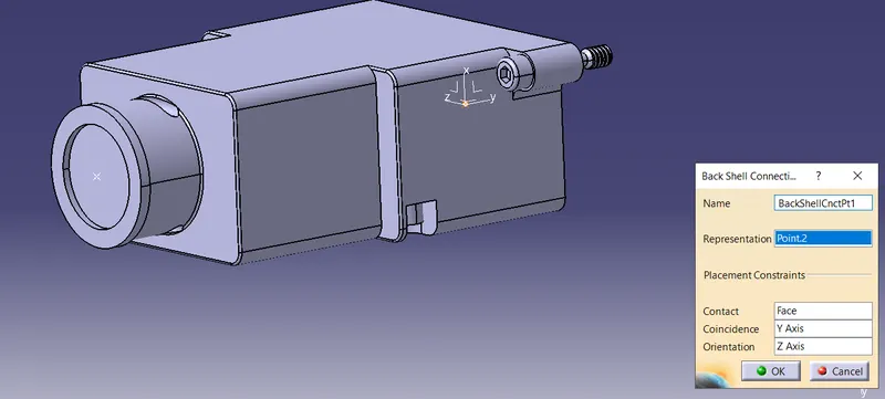
6.Define bundle connection point.
Q3. Create Following Corrugated tubes & Add them in Catalogue under “Slit COT” family.
|
Name |
ID (mm) |
OD (mm) |
Thickness (mm) |
|
15mm COT |
12 |
15 |
1.5 |
|
20mm COT |
17 |
20 |
1.5 |
|
35mm COT |
32 |
35 |
1.5 |
|
10mm COT |
7 |
10 |
1.5 |
|
5mm COT |
3 |
5 |
1 |
1.Switch to Electrical part design
2.Select Define protection Part
3.Click on part (on file name in specification tree)
4.Provide given parameters and bend radius as '1.5 x Outer Dia'.
Catalogue Creation:
1.new part →catalogue document → add family → give name → type → select Conduit → save.
2.Open part to add catalogue → store device command → select catalogue → family → Slit_cot_tube → ok
15mm COT
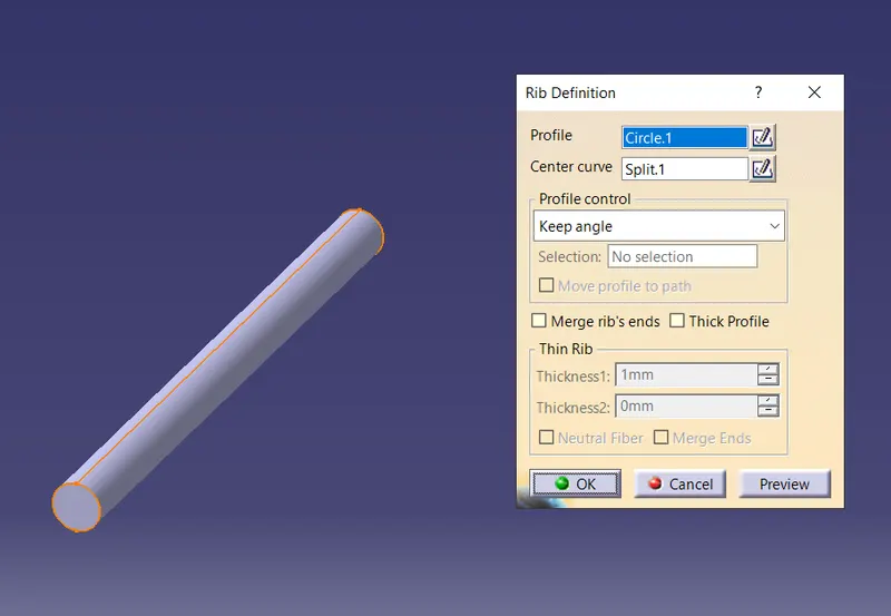
20mm COT
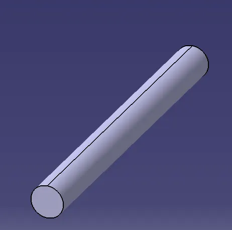
35mm COT
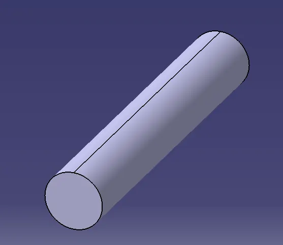
10mm COT
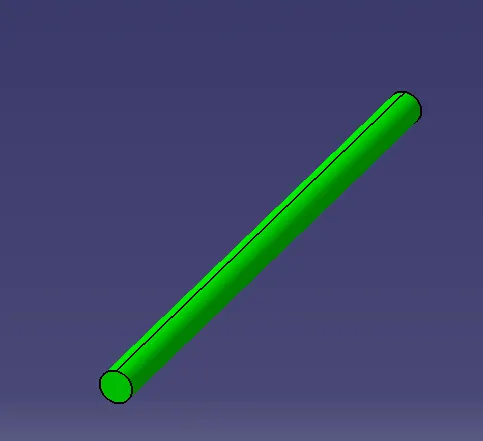
5mm COT
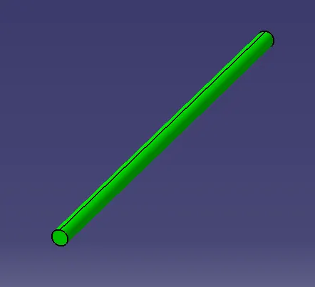
Following Corrugated tubes are created & and added them in Catalogue under “Slit COT” family.