Wiring harness routing & packaging Rules Week 3 Challenge
Q1. Download following cad data & define it as Electrical support using Electrical Part design Workbench. Define all the necessary properties.
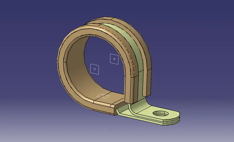
To Define the Geometry Parameters Create the following:
- Entry point and plane
- Exit point and plane
- Base/Bottom Plane
After the Geometry parameters are defined, in the electrical part design define it as a support part.
Q2. Download following Back shell cad data & define it as Electrical back shell using Electrical Part design Workbench. Define all the necessary properties.
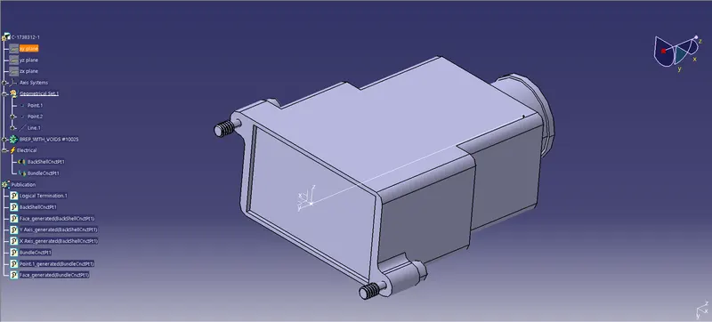
To Define the Geometric Parameters of the Backshell,
- Create a point and an axis system at the mating point.
- create a point at the bundle section.
Head on to the Electrical Part Design and,
- Define the component as an Electrical device using the command 'Define Backshell'
- Then define the mating point using the command 'Define Backshell connection point'.
- Lastly, Define the bundle point using 'Define Bundle Connection Poingt'.
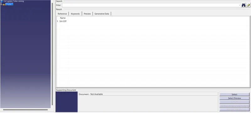
Q3. Create Following Corrugated tubes & Add them in Catalogue under the “Slit COT” family.
|
Name |
ID (mm) |
OD (mm) |
Thickness (mm) |
|
15mm COT |
12 |
15 |
1.5 |
|
20mm COT |
17 |
20 |
1.5 |
|
35mm COT |
32 |
35 |
1.5 |
|
10mm COT |
7 |
10 |
1.5 |
|
5mm COT |
3 |
5 |
1 |
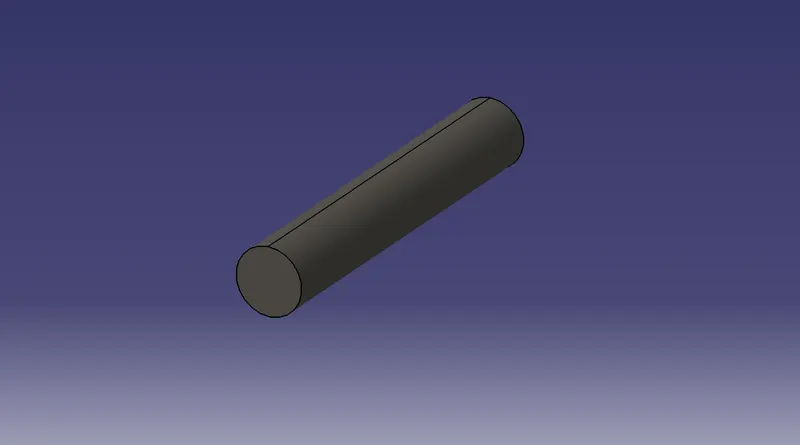
- Create Corrugated tubes as given dimensions by using the command define protection then click on the Part Body and then give the dimensions of inner diameter and thickness CATIA will create a rib-like structure.
- Now do the same for every other tube.
- Create a Catalog by going to New and Catalog Document, and add family as 'Slit COT' and save it.
- Now after creating the tubes, click on Store Device and add the device to the Catalog, by browsing it and select the family 'Slit COT'.