Wiring harness routing & packaging Rules Week 3 Challenge
P.CLAMP
Download the file from the source and convert the file format to CAD PART file format and save it in the required folder.
The next step is to define the CLIP as the ELECTRIC COMPONENT to define the clip we need to create the point and planes for the clip
Open the clip in the part workbench use the POINT command Define the point and repeat the same process to the other side of the clip.it can be used to define the Bundle Entry and Exit points. Then create planes by using the points select plane command and repeat the same process for the other side. need to create 3 planes 1 entry 2. exis 3. base plane.
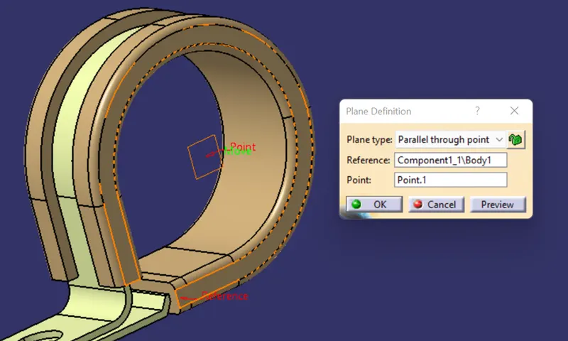
FIG plane creation
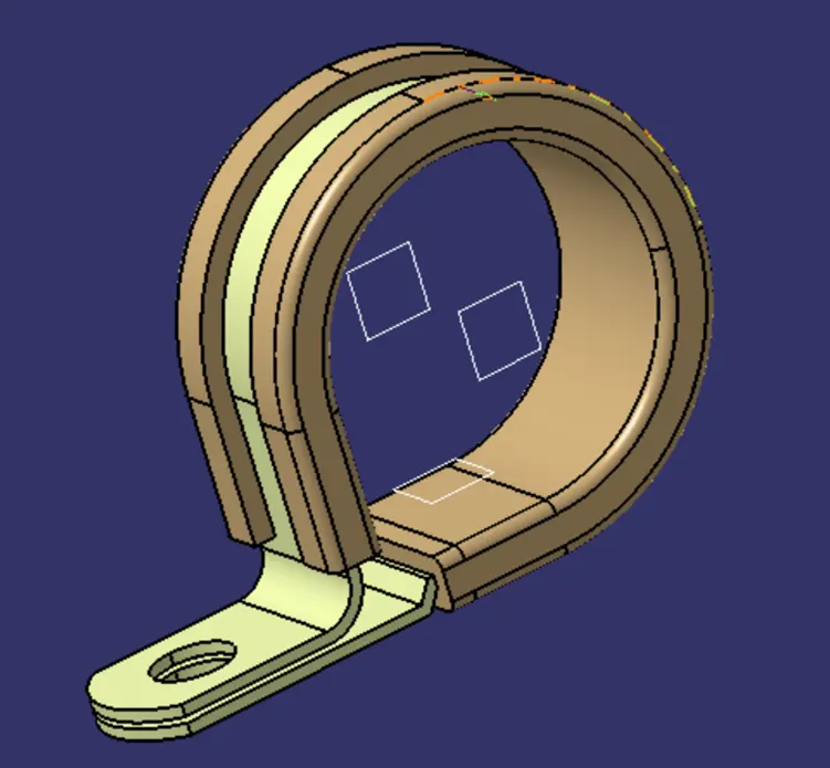
FIG final component to define as Electrically
Now move to the ELECTRIC PART DESIGN workbench. For defining the clip as an electric component we need to use the DEFINE SUPPORT PART option in the Electric part design workbench and select the component. And select the plane and point and second plane and base plane as well and repeat the same step to get the second step for the second point.
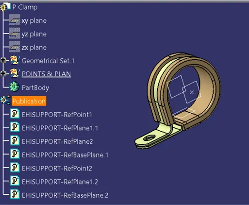
FIG defined as ELECTRIC DEFINED COMPONENT
Now save the component where ever it is required and add it to the CATALOG so it is easy to access.
ELECTRICAL BACKSHELL (1738312-1)
Download the component from the TE.com web page and covert the.STEP to .CATpart file saves the file to the location.
In general, backshells are the connections and protection part for the connectors so the same inputs is required for the back shell connectors. Like points and axis system.
Open the back shell in the part design workbench and select the points is component and create the point at the center for connecting to the connector and create another point at the bundle entry point.
Now move to the ELECTRIC PART DESIGN workbench and there is the command to define the Backshell select the DEFINE BACKSHELL option in the electric part design workbench and select the object. And define the bundle entry and connector entry points for the back shell. save the file and create a new family in the catalog and name as BACK_SHELL add the component into the catalog.
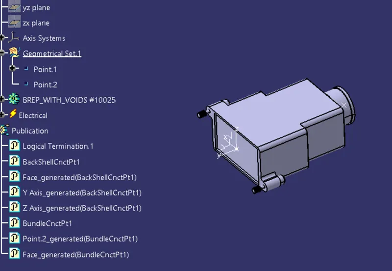
FIG BACK_SHELL
CREATING CORRUGATED TUBES and ADDING TO CATALOG
Corrugated tubes are used for the protection of wire harnesses.it consists of different dimensions in general they are based on the Bundle dimensions. The bending radius of corrugated tubes is 1.5 times of Dia of the bundle
If bundle DIA (D)then the radius of the tube is (1.5XD)
To create the corrugated tube open PART DESIGN WORKBENCH and name parts as dia of corrugated tube and COT. For example, 5MM_COT.that can be done for each separate component.
Then move to the electric product design workbench. Select the define protection part option and select the part or product and define the tube dimensions .
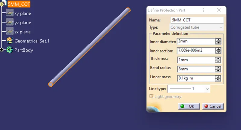
FIG corrugated tube creation
And create the catalog and name as SLIPCOT and created the family and save the parts in the catalog
Repeat the same process for 10mm,15mm,20mm,35mm.
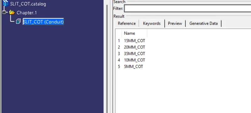
Fig added to catalog
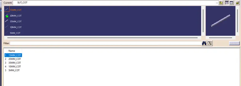
Fig Corrugated tubes opening from the catalog