Wiring harness routing & packaging Rules Week 3 Challenge
Aim :
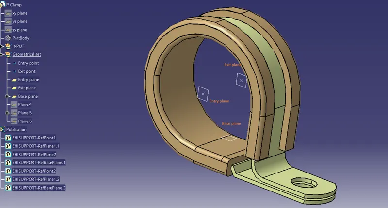
- To define given P clamp CAD data as an electrical support using electrical part design workbench & define all the necessary properties.
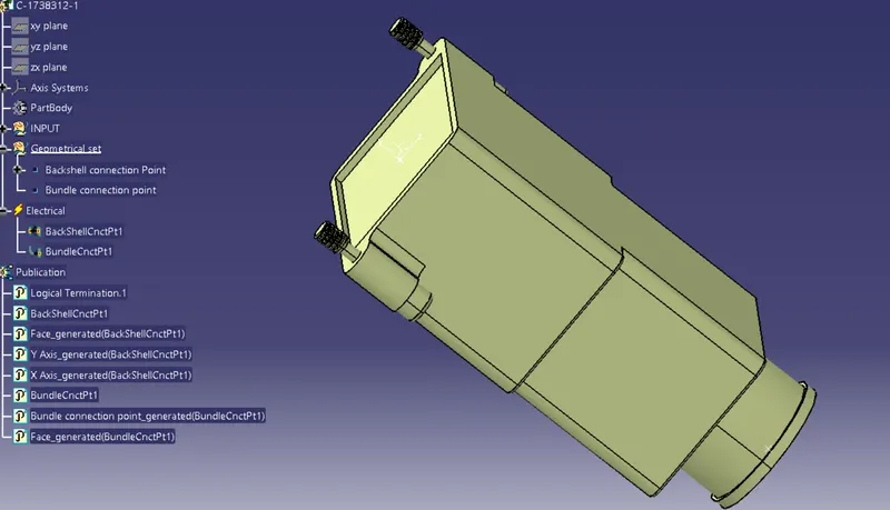
- to define given Backshell CAD data as an electrical backshell using electrical part design workbench & define all the necessary properties.
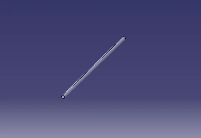
- To create COT tubes with outer diameters 15mm,20mm, 35mm, 10mm & thickness 1.5mm, and outer diameter 5mm & thickness 1mm and add them under catalogue in 'Slit COT' family.
Procedure :
a. Define the P clamp
1.Open the P clamp in part design.
2.Define geometry parameters which includes entry point & entry plane, exit point & exit plane, base plane.
3.Open the part in electrical part design workbench and define as a support by using define support command and input the parameters
to define entry points and planes
- Name : select the part.
- Point : Entry point
- Plane : Entry plane
- Plane : Exit plane (in the second plane definition)
- Plane : Base plane (in the base plane definition)
4. Define base and exit plane again using support command.
- Name : select the part.
- Point : Exit point
- Plane : Exit plane
- Plane : Exit plane (in the second plane definition which is selected by default)
- Plane : Base plane (in the base plane definition)
This is done because wire entry can be done from both sides.
5. Hence all the necessary properties are defined to the given P clamp as shown below.
b. Define the Backshell
1. Open the Backshell in part design.
2. Define geometry parameters which includes backshell connection point, backshell axis system and bundle entry point.
3. Open the part in electrical part design workbench and define Backshell connection point and input the parameters as below.
- Name : Select part
- Representation : Backshell axis system
- Contact : Connector contact face
- Coincidence : Y axis
- Orientation : X axis
4. Define bundle connection point using bundle connection point and input the parameters as below.
- Name : Select part
- Representation : Face (bundle entry face)
- Point : Bundle entry point
- Initial condition: Face (Face (bundle entry face)
5. Hence all the necessary properties are defined to the given Backshell as shown below.
c. Create Corrugated tubes
1. Click on file, open new, create part.
2. Go to electrical part design workbench
3. Select protective coverings command and select the part body from model tree, select type, and enter parameter (inner diameter, thickness, bend radius, line properties)
4. Save the part in catolog in conduit type and define the family as Slit COT type.
Conclusion : The P clamp, backshell are defined with necessary properties and corrugated tubes are created with desired sizes.