Wiring harness routing & packaging Rules Week 3 Challenge
Aim: The main aim of this challenge is to define the electrical parameters for the given components which are P-clamp and backshell, and also to create protective coverings for the bundles with different diameters and these must be added into the catalogue for accessing.
Procedure for defining the electrical parameters for the P-Clamp:
P-clamp is a supporting device which helps the bundle to enter and exit from it through the entry and exit planes and lie on the base plane.
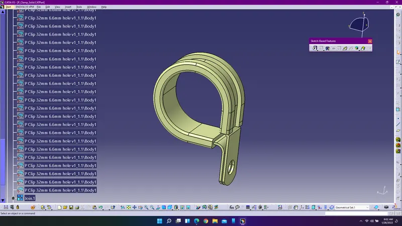
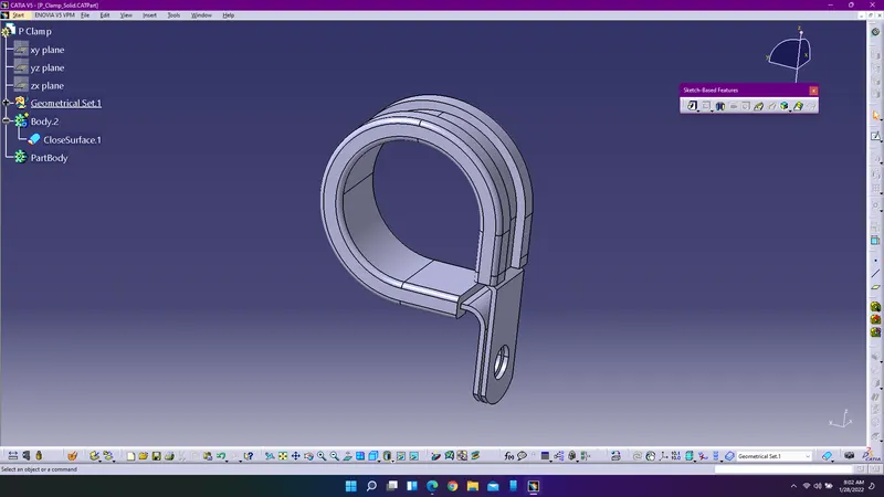
1. Convert the given surface component into solids by joining the surfaces and using close surfaces command in the part workbench convert the surfaces into solids.
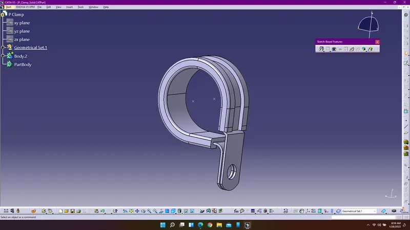
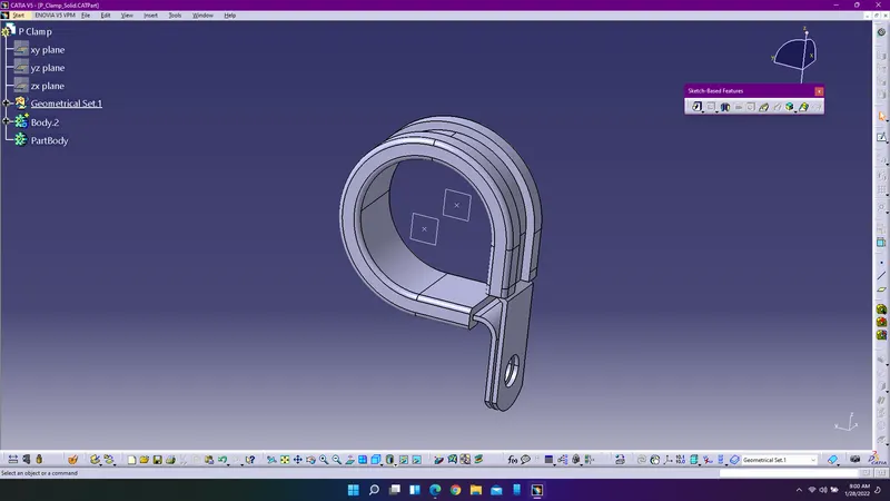
2. Create the entry and exit points for the bundles and add the planes at the points.
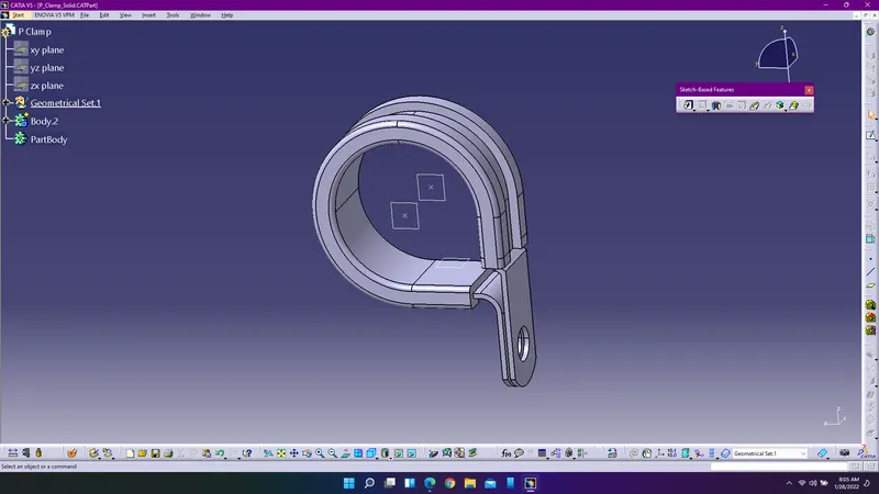
3. Create the base plane to support the bundle to lie on the surface by creating the plane which is parallel to the surface.
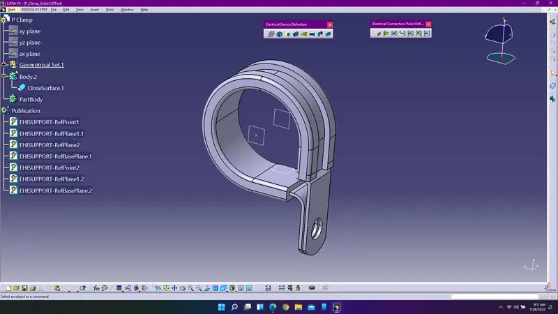
4. Enter into electrical part deisgn workbench to define the p-clamp electrically using define support command.
Procedure for defining electrical parameters for backshell:
Backshell is a retention device which is used to shield the wire connection points of the inter-connecting cable and the connector.
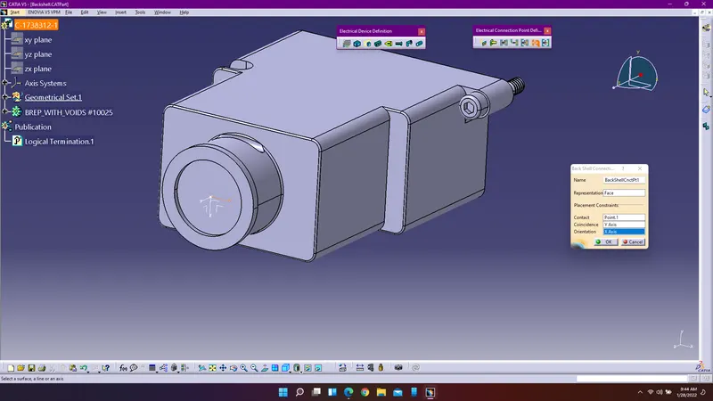
1. Create a point on the backshell where the bundle connects with the backshell and insert an axis system in the part design workbench using catia application.
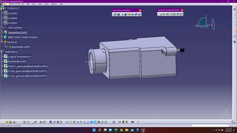
2.Define backshell and create the backshell connection point using define backshell connection command and define the electrical parameters for the backshell.
Procedure for creating procetive coverings:
1. Create a new catalogue document and create a new family as Slit COT for storing the protective coverings.
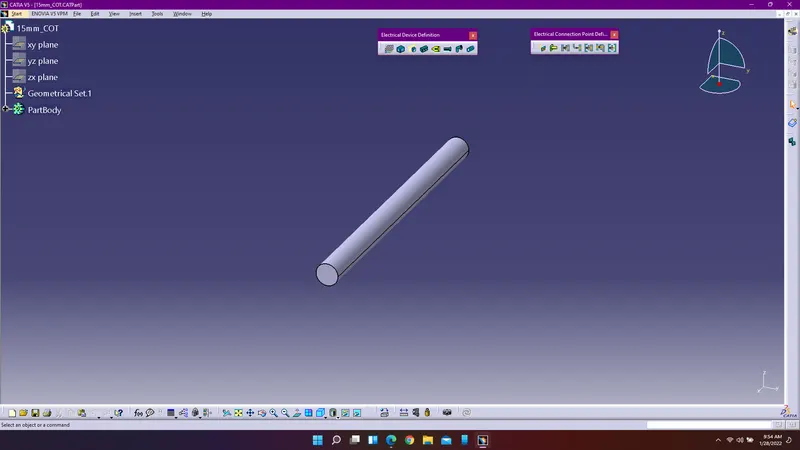
2. Enter into electrical part design workbench and use define protection part command to create protective coverings accordiing to various dimensions. Select store device command to store the protective coverings in the created slit cot family.
3. Follow the same above procedure to create the remaining protective coverings accordingly.