Photo Realistic Rendering
Design and Assembly of American Chopper Bike and Rendering using Solid Works Visualize
Aim: To design the parts of the American chopper bike using solid and surface modelling in Solid works and assemble them in Solid works and to provide a realistic render to the final assembly of American chopper bike using Solid works photo view 360 and Solid works Visualize.
Components:
Following mentioned are the parts of the American chopper bike:
- Transmission Belt.
- Kick Stand.
- Front Fender.
- Rear Fender.
- Oil Tank.
- Pedal.
- Chain.
- Front Wheel.
- Rear Wheel.
- Front Fork.
- Chassis.
- Engine.
- Gas Tank.
Approach:
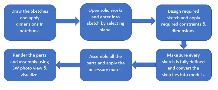
Procedure:
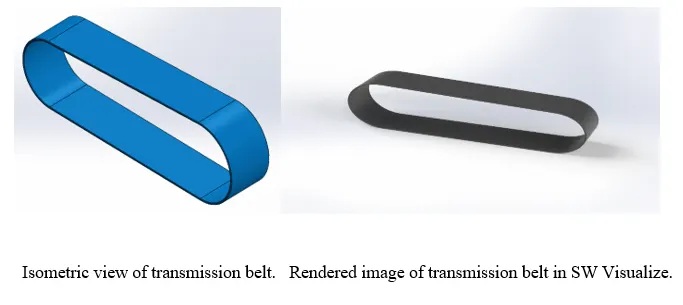
- Transmission Belt:
Transmission belt is connected to two shafts of the engine which helps in transmitting power.
- Features such as 2D Sketch-lines, curves and Boss Extrude and fillets are used.
- Design the sketch in the front plane and provide sufficient constraints in order to make the entire drawing to be fully defined.
- Constraints such as tangent to, coincident and horizontal were used to fully define the sketch.
- Apply the Boss Extrude to convert the sketch from 2D to 3D and apply the required fillets to the edges of the Transmission Blet.
- Rubber is provided as material and applied required aesthetics.
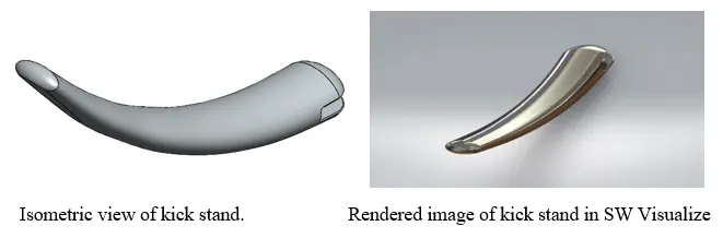
- Kick Stand:
Kick stand is connected to the chassis of the American chopper bike which allows to rest the bike on the ground and ensure the vehicle to not to slip during rest.
- Features such as 2D Sketch-Lines, Ellipse, Spline and Loft, Dome and Split are used.
- Design an ellipse in the front plane and constraint it by providing dimensions to it and from reference which is the origin.
- Create a spline in the mid plane from the center of the ellipse which is located in the front plane and provide required constraints and make sure the sketch is fully defined by providing weights and angles to the handles of the spline.
- Create a plane at other end point of the spline and design an ellipse and provide required dimensions and appropriate constraints.
- Use the Loft Extrude option to convert the sketch into model and apply dome at the both faces of the ellipse.
- To provide the flat surface to rest the bike a line is drawn, with the help convert entities the ellipse is converted and transformed it into a construction line, with the help split tool the flat surface is created at the bottom.
- Provided the chrome metal to the Kick stand which is designed.
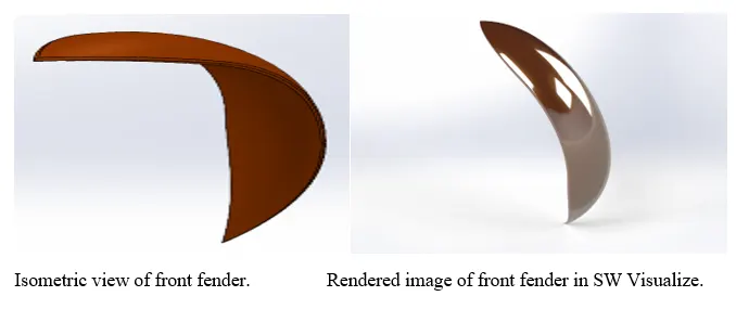
- Front Fender:
Front Fender helps in preventing the bike from dust and dirt from the front wheel and provides a great appearance to the chopper.
- Features such as 2D Sketch-Lines, Curves, Revolve Extrude, Fillet and Split are used.
- Design the appropriate sketch in the front plane and provide required dimensions from the origin and apply the required constraints and ensure the sketch is fully defined.
- Using revolve extrude option the sketch is converted into the model.
- Split tool is used to trim the unnecessary portion of the fender.
- Applied the fillets to the edges of the fender and provided a sienna material to it.
- Rear Fender:
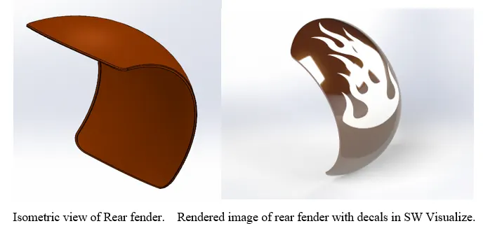
Function of Rear fender similar to the front fender but the dimension is not similar to the front fender as rear wheel is large in diameter which helps in providing great grip to the bike.
- Features such as 2D Sketch-Lines, Curves, Revolve Extrude, Fillet, Split and Shell are used.
- Design the appropriate sketch in the front plane which is required for the rear fender and provide the dimensions from the origin and apply the appropriate constraints to the sketch.
- Using revolve extrude option the sketch is converted into the model.
- Sketch is drawn in the top plane and provided with dimensions from the reference and split is used to provide great appearance to the rear fender.
- Shell is used to create some hollow portion to the inner face of the rear fender.
- Fillets were applied to the edges of the rear fender and sienna material is applied for the good appearance and decals are provided for the rear fender which allows to look more realistic.
- Oil Tank:
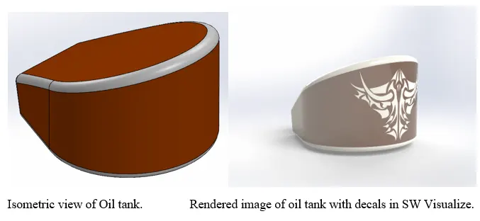
Oil Tank is used to store the oil which helps the bike to cool the engine and also allows for lubrication.
- Features such as 2D Sketch-Lines, Boss Extrude, Fillet, Combine, Shell are used.
- Sketch in top plane and ensure it is fully defined and apply boss extrude option.
- Sketch in front plane and provide dimensions and constraints to make the sketch fully defined and using boss extrude mid plane option convert the sketch into model.
- Use Combine option to combine both the solid body entities and which provides a single solid body which is common in both solid entities.
- Apply fillets to all edges and apply shell to create hollow portion inside the oil tank and sienna painted material is applied for good appearance and decals are provided for realistic look.
- Pedal:
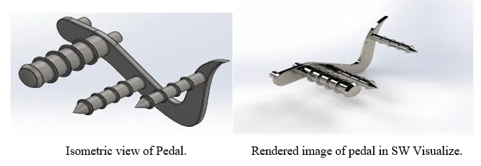
Pedal is connected to clamp provided to the chassis and helps the rider to change the gear and to apply the brakes and to rest the foot on it.
- Features such as 2D Sketch-Lines, Circles, Splines, Boss Extrude, Fillet, Chamfer, Dome, Linear Pattern are used.
- Design the appropriate sketch in front plane required for the pedal using lines, splines and curves and these are constrained and fully defined using dimensions and splines handles are provided with both angle and weight dimensions and used constraints to fully define them.
- Circles were drawn in the sketch and fully defined by providing them with dimensions and these circles helps to rest the foot on them and circles on the other face allows the pedal to sit in the clamp which is provided in the chassis.
- Using Boss Extrude the sketch is converted into model and chamfer is applied to create the sharp and fine edge to circles which are created and fillets were provided to the edges of circles and pedal.
- Dome is used for the circle which is having large diameter and linear pattern is used on the large diameter circle and small diameter circles on the side of the pedal and Chrome material is added to the pedal to give a nice appearance.
- Chain:
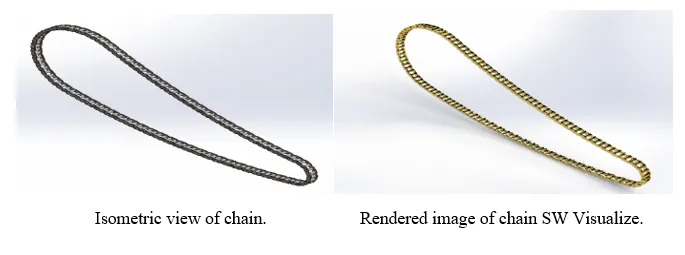
Chain is connected to Rear wheel Sprocket and Engine Sprocket which allows to transmit rotary motion to the rear wheel. Best part to learn when you are working with this where you will learn using blockchains and pattern them.
- Features such as 2D Sketch-Lines, Curves, Circles, Slot, Blocks, Mirror, Boss Extrude, Curve Pattern are used.
- Complete sketch lies in front plane with the help of curves the sketch is drawn from the origin and constrained them and provided with dimensions to fully define the sketch.
- Create Blocks by sketching them in front plane and make them as block chain which are imported and extruded every time.
- Blockchains are imported from the library and align them in the sketch by providing constraints and extrude them using Boss Extrude and use curve pattern to complete the chain.
- Use Mirror option and select all chain links to mirror them to other side of the links.
- In this chain part totally 130 pins and 260 chain links will be created.
- Gold material is applied to the chain.
- Front Wheel:
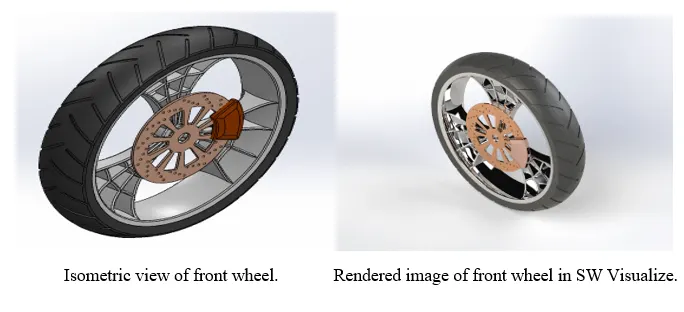
Wheels helps to ride the bike and provides the grip with the ground. Wheels majorly consists of Rim, Rotor, Caliper, Tire.
- Features such as 2D Sketch-Lines, Circles, Splines, Trim, Offset Entities, Boss Extrude, Revolve Extrude, Combine, Circular pattern, Cut Extrude, Fillets, Chamfer.
- Design Sketch in the front plane and constrain them and fully define using dimensions and use revolve extrude option to create rim for the front wheel.
- Create Web design spokes for the rim in the right plane with the help of splines activate the handles of the splines and provide the angular dimensions and weights to the handles of the splines and constraint them by providing dimensions with the origin.
- Sketch web design on the extruded splines using offset entities and circles and trim features create the web design and make the sketch is fully constrained and extrude them using boss extrude.
- Apply Circular Pattern and use 3 instances inside the rim and apply the combine option to create a beautiful front wheel.
- Sketch in front plane to design the tire on the rim, design the sketch and apply the required dimensions and provide constraints to fully define the sketch.
- Sketch the grip for the tire in the front plane and make sure the sketch is fully defined and use cut extrude by selecting offset option remove the material on the tire.
- Apply Circular pattern of sketch to provide grip to the entire tire.
- Rotor and caliper were designed in the front plane and required curve pattern were performed on the rotor.
- Fillets and chamfers are provided to the edges of the caliper.
- Applied Chrome material to the rim and spokes and Copper is applied to the Rotor and Sienna for the caliper and Rubber for the Tire.
- Rear Wheel:
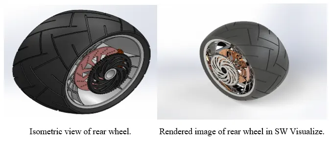
Rear wheel consists of sprocket which is driven by the chain, which is connected to the engine sprocket and functions similar to the front wheel and rear wheel provides great grip with the ground while riding bike.
- Features such as 2D Sketch-Lines, Curves, Circles, Splines, Trim, Revolve Extrude, Boss Extrude, Offset entities, Circular Pattern, Combine, Cut Extrude, Fillets, Chamfer.
- Design sketch in the front plane and using revolve extrude option convert the sketch into model and create the spokes in the right plane using splines.
- Activate the handles of the splines and provide weights and angular dimensions to the splines and use offset option with the help of vertical constructional line which is coincident to the origin.
- Extrude the splines created in the rim and create web design to the spokes.
- Sketch the web design using circles, curves and trim option to rid out of excess entities and extrude them on the spokes.
- Use circular pattern and consider 3 instances of the spokes and combine them.
- Design the rotor and extrude it and make appropriate sketches on the rotor and use linear pattern, select the linear pattern entities and make circular pattern on the rotor.
- Design caliper on the rotor and apply chamfer and fillets to the caliper on both sides.
- Create sketch in the right plane to design sprocket and use appropriate sketches and apply circular patterns on the sprockets on which chain lies on it.
- Chrome material is applied to the rim and copper is applied to the rotor and sienna is applied to caliper and chrome to the sprocket.
- Front Fork:
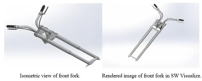
Front Fork is connected to the chassis and rear wheel of the bike which helps to steer the vehicle and consists of head lights, brakes, handles.
- Features such as 2D Sketch-Lines, Circles, Curves, Splines, Revolve Extrude, Cut Extrude, Boss Extrude, Sweep, Project Curve, Combine, Mirror, Linear Pattern, Fillet.
- Sketch the Fork in the front plane using revolve option extrude one of the forks.
- Sketch the top plate of the front fork in right plane and use boss extrude to convert the sketch into model by using offset option.
- Use linear pattern to create the second plate for the front fork.
- Sketch a circle in front plane which connects the front fork and extrude it using boss extrude.
- Sketch the head lights and use revolve extrude and convert it into model and apply cut extrude to create light, apply dome and fillet to the head light.
- Copy/Move the head light and exactly locate the head light at the appropriate position.
- Design splines in the top plane and use project curves to get the exact sketch for the handle and apply sweep option to create handle.
- Design handle grips for the front fork by creating new plane at the end of the handle and apply revolve option for extruding.
- Sketch Clutch and brake bars/handles and extrude them and using project curves option sketch the brake wires.
- Use sweep to extrude the brake wires and apply mirror to mirror the entities.
- Use combine to combine the mirror entities and apply chrome material to it, apply lights to head lights and provide some illumination to it.
- Chassis:
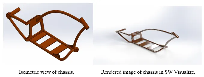
Chassis is the major part of the bike, which bears the complete load of the bike on it and connects to all parts of the bike, the chassis must be rigid and robust to ensure not to damage the bike.
- Features such as 2D Sketch-Lines, Curves, Circles, Splines, Sweep, Boss Extrude, Cut Extrude, Split, Project curves, Dome, Fillet, Chamfer.
- Create sketch in front plane and top plane and right plane make sure they were fully defined and using project curve the required sketch is obtained and sweep is applied to extrude the sketch.
- Mirror the extruded part using front plane and sketch the back plate in the right plane and apply necessary constraints and dimensions and make sure it is fully defined.
- Use fillets and chamfer to the extruded back plate and sketch the curves which connects to the hub of the rear wheel and using sweep option both curves are extruded and connected to the hub and apply a dome to the hub.
- Sketch the curve which connects the backplate and front fork and apply sweep for it and sketch another curve which supports front fork and chassis using sweep option extrude it.
- Sketch the pedal holders/clamp in the front plane on chassis and extrude it and sketch the kick stand holder by converting entities and use boss extrude.
- Sketch the plates required to mount the engine on the chassis and extrude them by using boss extrude.
- Apply sienna material to the chassis and apply fillets and chamfer to the back plate of the chassis.
- Engine:
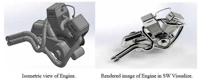
Engine is the heart of the vehicle which allows the vehicle to run and consists of moving parts which makes the engine to vibrate, to control these vibrations the support must be robust and rigid which helps in stopping the vibrations to pass and casing should be rigid and provided with fins so that it cools the engine quickly.
- Features such as 2D Sketch-Lines, Circles, Curves, Splines, Boss Extrude, Cut Extrude, Project curve, Composite curve, Linear Pattern, Circular Pattern, Sweep, Revolve Extrude, Dome, Fillet, Split.
- Create the basic sketch of the engine in the final plane and provide required constraints and dimensions to the sketch and extrude it using boss extrude.
- Sketch the shafts which is connected to the engine on the other face, those shafts help in power transmission with the help of belt.
- Provide grips to the shafts and use circular pattern to pattern the circles drawn on the shafts.
- Sketch the piston holder and provide fins to it using linear pattern, make appropriate curves using project curves and composite curves for the exhaust and use sweep to extrude it.
- Apply dome to the piston holder and sketch a sprocket which drives the rear wheel by connecting to the chain.
- Design the oil tank holder on the engine and apply fillets to it and use combine to combine both engine and Oil Tank holder.
- Design a dynamo which connects to the engine and legs for the engine which allows to mount the engine on the plates of the chassis.
- Sketch the wires which are connected to the handle and extrude them using sweep extrude.
- Apply fillets where it is necessary and use split to get rid of extra portions and apply cast iron/platinum material to the engine.
- Gas Tank:
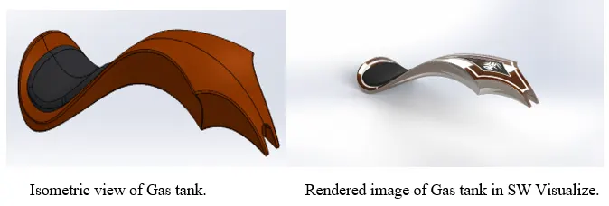
Gas tank stores the fuel and allows the rider to sit on it in a comfortable position, which is connected to the chassis.
- Features such as 2D Sketch-Splines, Lines, Curves, Surface sweep, Surface Loft, Surface trim, Boundary surface, knit surface, Fillet, Cut Sweep, Shell.
- Sketch the splines in front and right plane and activate the handles and make sure the sketches are fully defined.
- Use Surface sweep to create surface and use surface trim to trim the surfaces and create sketch using spline in the front plane and create surface using surface loft.
- Sketch the lines and splines and create surface using boundary surface and use mirror to mirror the surface to the other side and apply knit surfacing option to knit the surfaces.
- Create the seat portion by sketching in top plane and use split tool and create surface and apply fillets to it.
- Create boundary surface to sit the gas tank on the chassis and apply fillets to the edges.
- Use surface loft and close the surfaces and create solid entity from it and apply fillets to the gas tank.
- Apply sienna material to the gas tank and apply decals to it which helps in realistic look.
- Assembly:
Import the parts of the chopper and apply the appropriate mates and fully define the assembly, suppress the mates which are necessary which makes the assembly over define and apply rendering in photo view 360 and solid works visualize.
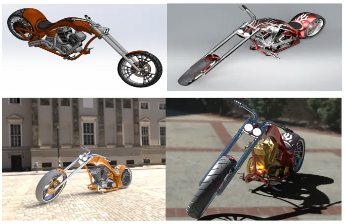
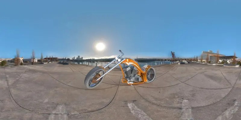
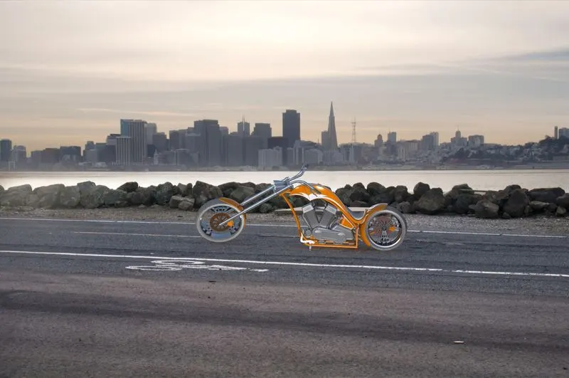
Front, top, rightside and Isometric & Camera views of rendered American chopper bike:
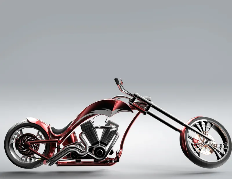
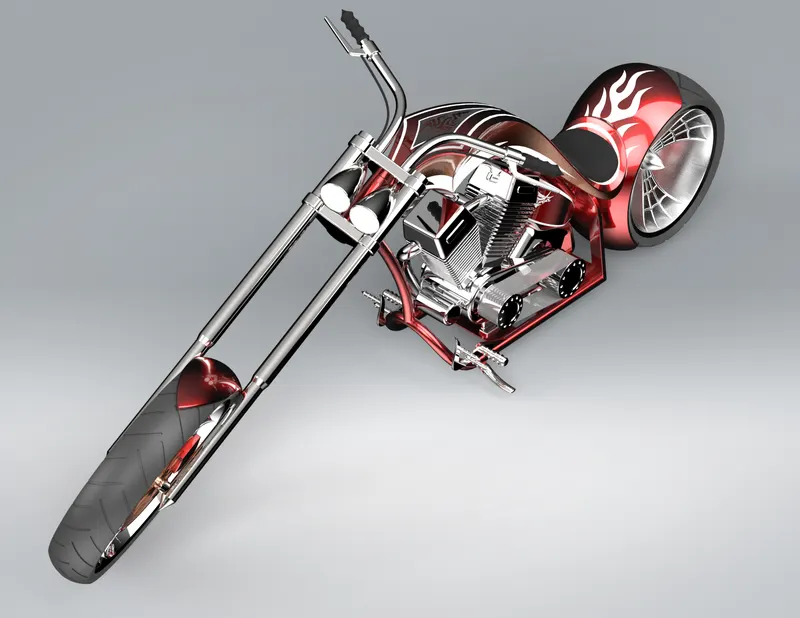
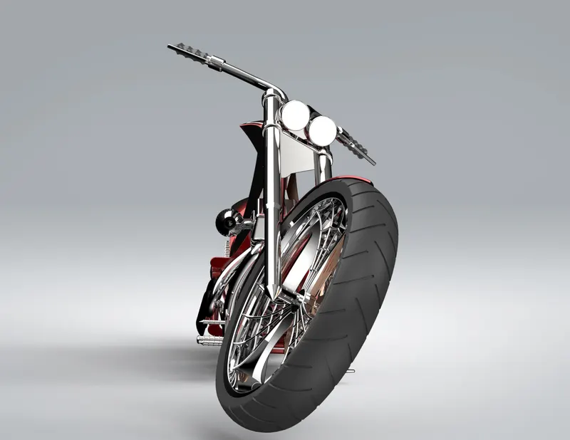
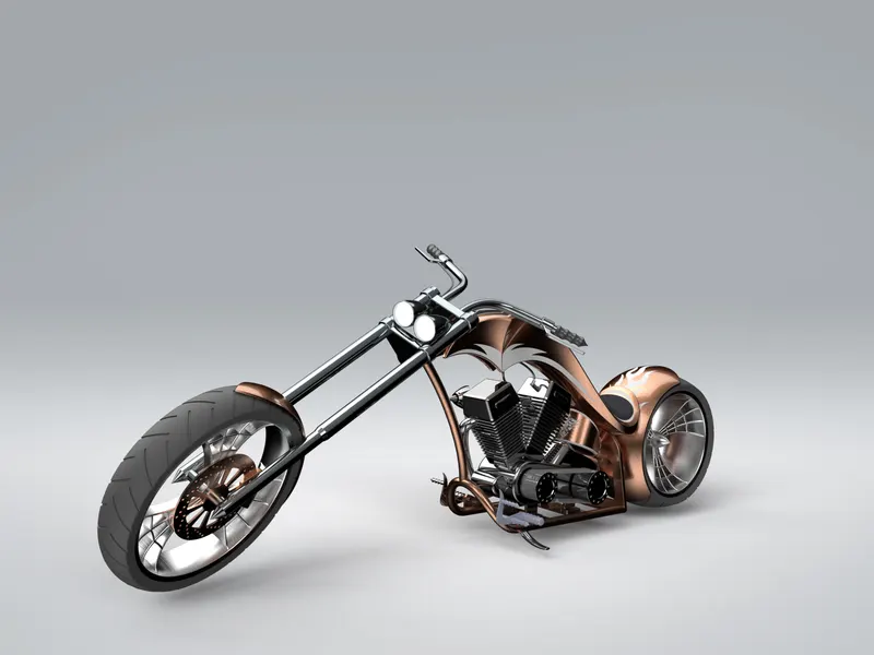
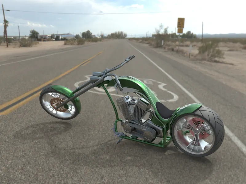
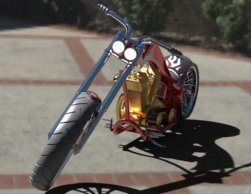
Some of the more realistic rendering of American chopper bike:
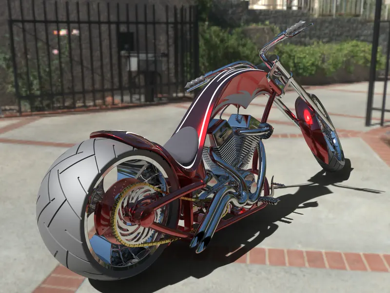
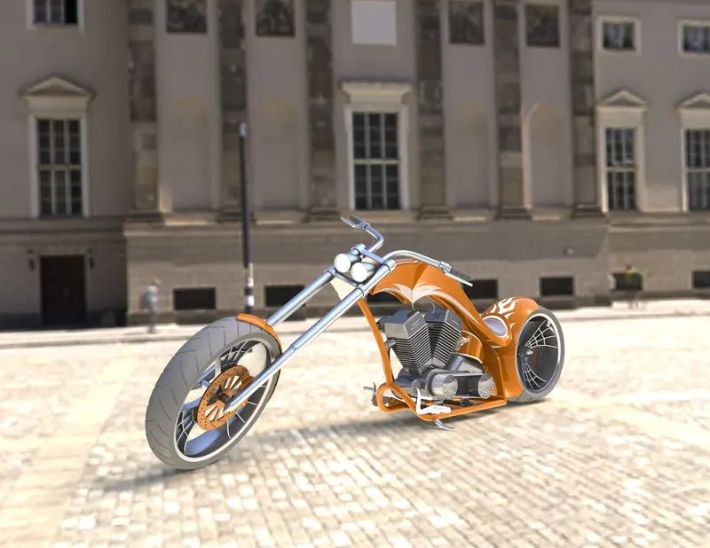
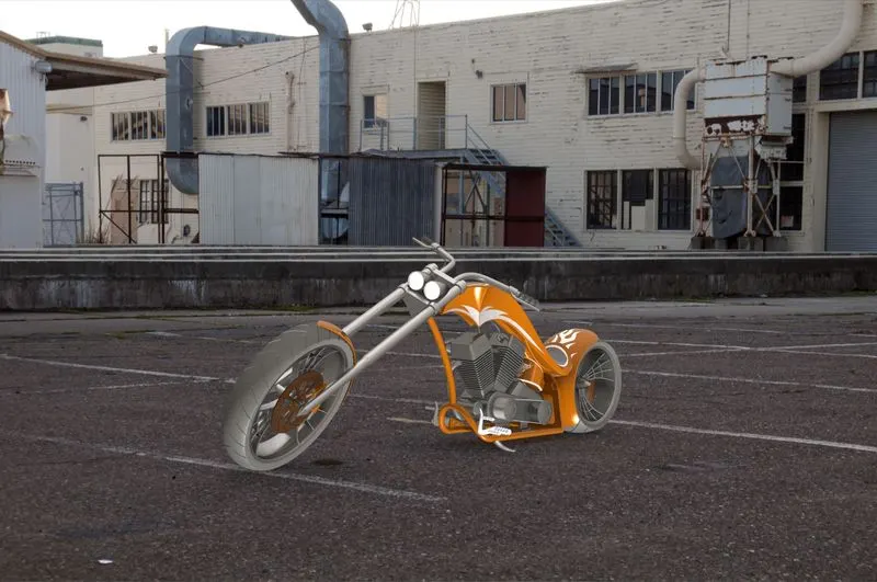
Renders using Photo view:
Conclusion:
American chopper is designed and assembled using solid works and rendering were applied in both solid works photo view 360 and visualize.