Wiring harness routing & packaging Rules Week 3 Challenge
Q1. P-Clamp
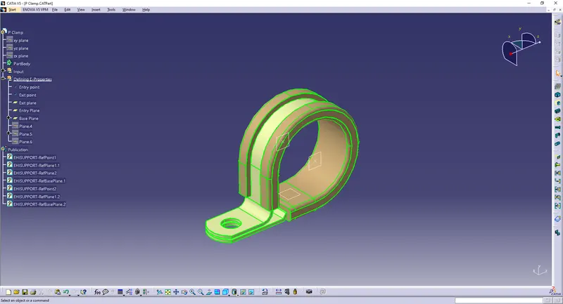
To define the P-clamp as an electrical support, the following procedure is followed.
- The first step is to download the P-clamp.igs file or P-clamp.stp file and opening it in catia V5.
- We know that the wiring harness bundle is going to enter the p-clamp from one side and exit it from the other, and vice versa if the wire is sent in the opposite direction.
- Now, we open the part design workbench and create entry and exit points by using the point command and using the circle/sphere/ellipse option.
- Similarly we create entry and exit planes at their respective points and also create a base plane where the wire rests on the support.
- Then we open the electrical part design workbench and and start by defining the p-clamp as an electrical support.
- We designate the entry point, entry plane, then the exit plane and base plane and do the same thing teice as the harness bundle may enter from either of the two sides.
- We save this part which has been defined as an electrical support.
Q2. Backshell
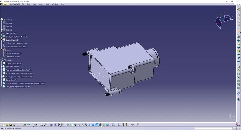
To define a backshell as an electrical part, the following procedure is followed.
- The first step is to download the backshell part as a .igs or .stp file. and open it on catia V5
- We know that the backshell is an electric component and it contains a bundle entry point and a connector connection point.
- We go to the part design workbench and create a point at the center of the connector end and another point the center of the bundle entry end.
- The next step is to create an Axis system at the connector end point that we just created, and the axis system must follow the same axis system as our electrical connector.
- We then move onto the Electrical part design workbench and define the backshell as an electric component by selecting the "Define Back Shell" option.
- We then use the "Define Backshell connection point" option and select the point, connecting face, the coincidence axis and the orientation axis.
- Next, we use the "Define Bundle Entry point" option and select the face point and connecting face ofthe bundle entry.
- Now the backshell is completely defined as an electrical component and we save the part
Q3. Corrugated Tubes
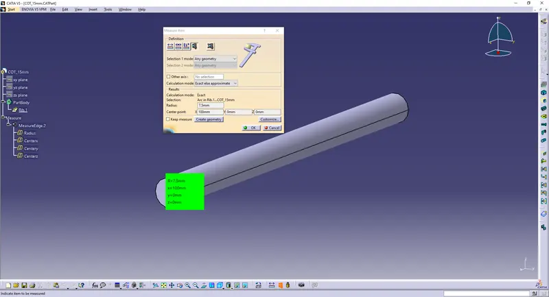
I have followed the following steps in the creation of the 5 cot tubes mentioned in the question but i am explaining the procedure only for one cot tube of 15mm diameter.
- First we open catia V5, create a new part and go to electrical part design workbench.
- Now we use the Define Protection part option and select the type as corrugated tubes.
- We enter the inner diameter value as 12mm as the thickness is 1.5mm which makes the outer diameter of the cot tube 15mm.
- We calculate the bend radius value of the cot tube by multiplying the outer diamter by 1.5, and in this case it is 15*1.5 which is 22.5 so we can approximate the bend radius value to 23 and we click Ok.
- We then save this part and add it to a new catalogue document and add a family in the catalogue called COT_Tubes.
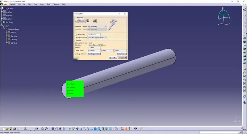
Repeating the steps we create more cot tubes of 20mm, 35mm, 10mm and 5mm outer diameters and add them all into the catalogue document.
15mm
20mm
35mm
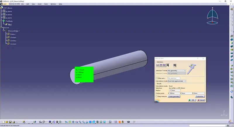
10mm
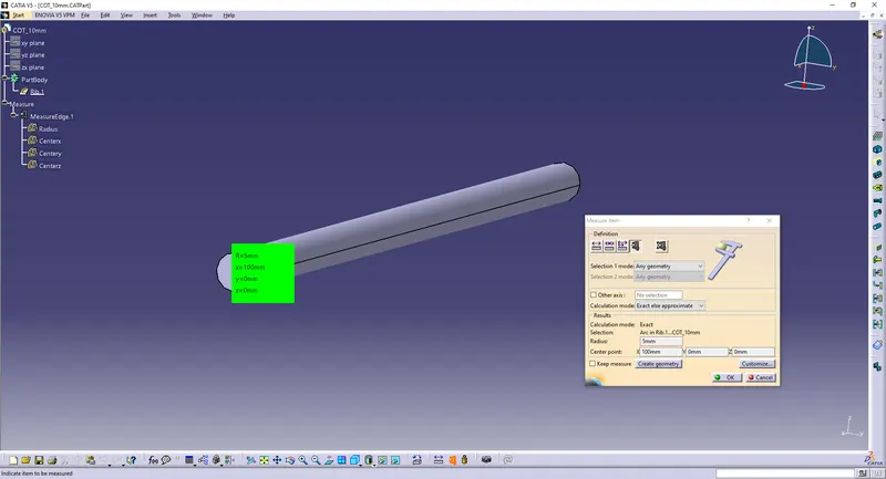
5mm
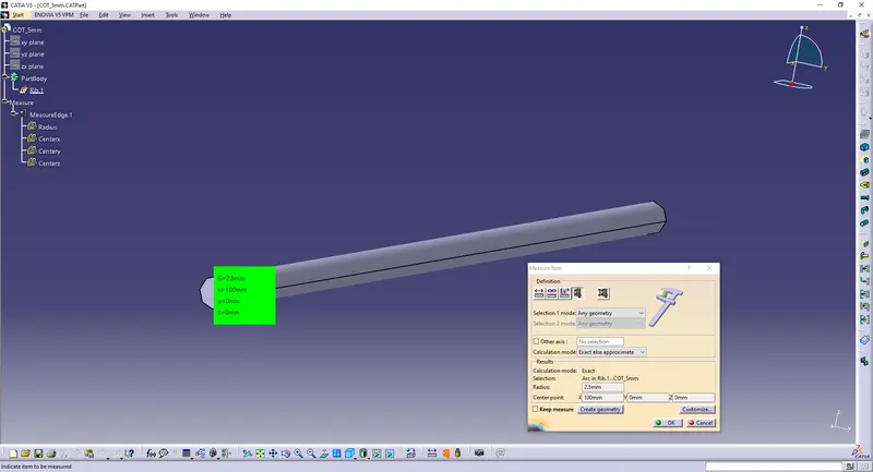
Cot tubes are attached in a compressed .rar folder named COT tubes. the catalogue is inside the same folder.