Radar Mast & Final Assembly of Yacht
Designing and Assembly of the Predator Yacht
- Objective- The objective given to me for this project was the designing and assembly of the Predator Yacht. This consisted of designing of the following parts - Propeller, Radar, Hull, Garage door, Front seats, Middle seats, Rear seats, Superstructure and the Radar mast. Then to assemble the above mentioned parts to complete the final assembly of the predator yacht and the rendering of the yacht.
- Introduction- The designing of the Predator Yacht started with the creation of each part individually using a software called Solidworks 2019. The first part created was the Propeller followed by the Radar, the Hull, Garage door, Front seats, Middle seats, rear seats, the superstructure, and finally the radar mast. These parts were first designed with the appropriate features and appearance(material) then assembled into one assembly which helped us finish the complete model of the Predator Yacht. This assembly was then rendered for a photo-realistic view in the appropriate environment. I learnt a lot doing this project in using the software Solidworks 2019 and also all the capability it has in creating complicated parts and assemblies. I have further explained the creation process in this report.
- Design Methodology-
- Description-
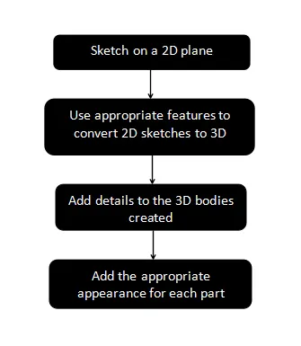
Sketches
The first step in designing is creating the appropriate sketches on a 2D plane with the necessary dimensions and constraints. We must fully define the sketches that are created to move forward to the next step. I learnt to use a lot of new sketch tools ranging from basic tools like lines, arcs, circles, rectangles etc to complex curves like splines and projected curves. A projected curve is sketching on two separate 2D planes to create a sketch which exists in the 3D quadrants which can be used to design complicated geometry, for example in this model, I used the projected curves created to extrude surfaces which helped in creating the shape of the outer body of the yacht.
Features
The next step in designing is to make the sketches on the 2D planes come out into the 3D. This is done by using features like extrude, revolve, extruded boss, extruded surface, lofted surface, etc. These features make fully defined closed sketches come out of the plane giving us solid body geometry in 3 dimensions. Some other features I used were shell which can make a solid body hollow, fillet command which helps us give a smooth rounded finish on sharp edges, chamfer command which helps us chamfer the sharp edges of the solid bodies. Extruded cut and revolved cut helps us in removing excess material from out solid bodies which is also done by creating sketches on the 2D plane and then using these sketches to remove the material. another very useful command which was used a lot in designing the Yacht was the linear pattern in creating the multiple windows on the sides. Also the Feature that made this design possible was the projected curves. They helped us in designing the complex shapes and surfaces of the outer body of the hull and the superstructure.
Appearance
The next step after we create the perfect solid body is to give these solid bodies their materials and appearances. we have a wide variety of materials to choose from on solidworks 2019. We must give the appropriate materials to the parts for it to look realistic. We can also give these materials we choose colors of our choice.
Assembly
The next step after we have modeled all the parts is to import all these files into a new assembly. We first import the Hull then fix the superstructure onto the surface of the Hull. Then we fixed the radar mast into its position. In a similar manner we then add the necessary constraints to fix the front, middle and rear seats into their respective positions. Then we fixed the garage door and the three propellers into their positions with their functional movements enabled. Finally we fixed the radar onto the radar mast. We fix the entire assembly into one part and make any changes and corrections to the individual parts if necessary.
Render
This is the last step where we use photoview 360 which is an inbuilt rendering tool in Solidworks 2019 to make our Assembly look as realistic as possible. Rendering basically makes the materials look how they do in real life by giving them their physical properties. Another Rendering software I used to finish the final render was Solidworks visualize. This software helps us add a lot more appearance to the model and also lets us place out assembly in the appropriate environment or scene. This gives us a realistic feel.
Parts modeled with a brief about their features.
Blueprint setup
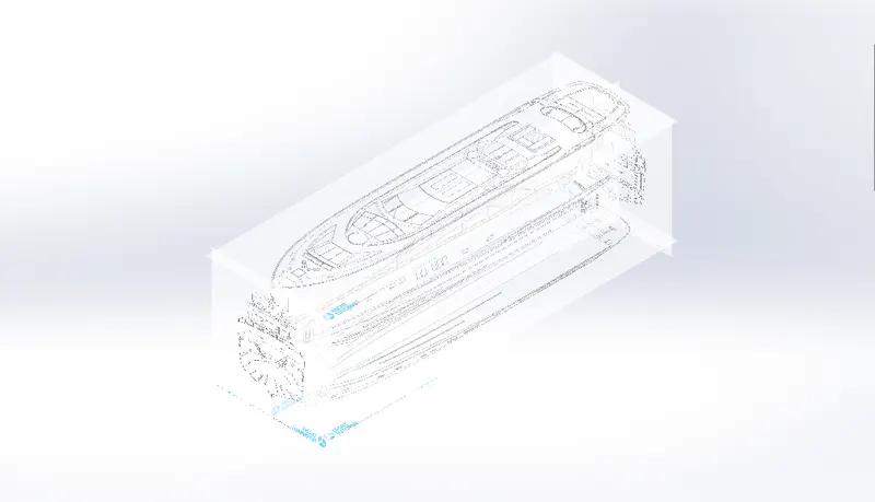
The first step in creating complicated surface bodies like the predator yacht is to save all the sketches of all the views(front, side, back, bottom and top) and creating any necessary reference planes approximate to the dimensions of the yacht and inserting all the sketch pictures of all the views. This is going to be very useful to us in sketching all the curves to create surfaces for all the parts. We first save this blueprint and create all our symmetric parts using this blueprint.
Propeller
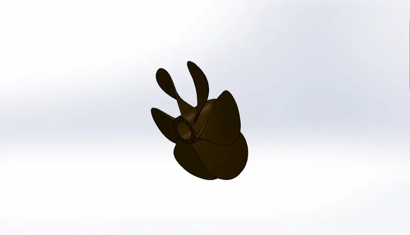
The first part I designed was the propeller. I started this by making a sketch and revolving it to make the rotary portion of the propeller. Then we create a reference plane and create a sketch for blade of the propeller. Then we create another sketch on the top plane and we make a lofted boss up to the new plane using the sketch made on the new plane. We then make fillets on the lofted boss to give the blade a shape. Then we cut a hole for fixing the propeller onto the driver. Finally we give fillets over the one blade we created and then use the circular pattern to make the blades all around the propeller.
Radar
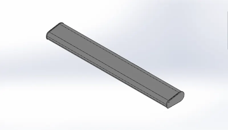
We first start by sketching on the mid-plane by creating the shape of the radar. Then we create another extrude at the outer edge. We make another profile on the outer face of the radar and pattern four screws. We apply the appropriate fillets and mirror this body with mid-plane as the reference. Finally we create a hole on the bottom face of the radar for the purpose of fitting it onto the Radar-mast.
Hull
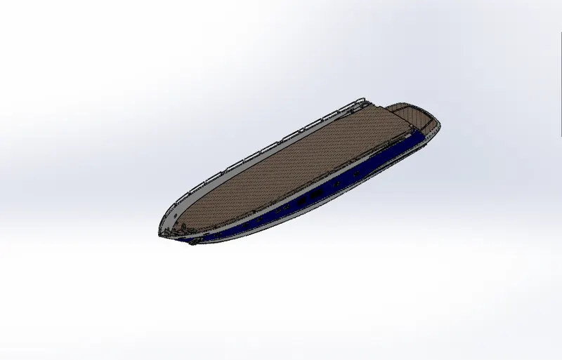
We are going to first design one half of the hull across the midplane and then once we create all the features on one side we intend to mirror the whole body across the midplane to give us the whole body of the hull. We start by creating the projected curves needed to create the outer surface with the desired shape of the yacht. Then use the lofted surface option to create the side surface of the yacht. Then make another sketch and create a lofted surface which gives us the bottom surface of the yacht. Then we trim all the extra surfaces. We create a few more surface extrudes and lofted surfaces to complete the backside of the yacht, and we also trim all the extra surfaces. The next step is to fill all the empty spaces between the surfaces extruded to get closed surfaces using the surface fill option. We then knit all the created surfaces and move on to extruding more surfaces to add details to the backside of the yacht. We shell the front of the yacht to create the cable holes and then we boss extrude from the entire hull from the mid-plane to one side to get a solid body geometry. We then give all the necessary fillets and chamfer to give the created body a good finish. And add more details to the shape with cut extrude and boss extrude options. We then create all the windows and use linear pattern to place all the widows in the appropriate positions and add details to the windows by using swept boss to create a window frame. Then we create the cable wires and the holders in the front side of hulls surface. The next step is to create all the railings which is done by using the projected curve option by projecting the railing reference across the entire body of the hull. The next step is to add more details to the railings and filling in all the gaps between the railings using more extruded boss. Then we give the necessary fillets and move on to the backside of the yacht. We now start designing the rods holding the propellers on the backside of the yacht by creating one right in the center and using linear pattern to copy this created propeller onto backside surface. We then create the anchor on the front side. The next step is to create cut extrudes for the garage and we remove this whole solid body out of the back of the hull. We will design the garage door using this solid body which we removed and saved. The last step is to create the steps on the side of the hull leading back to the garage. And after we have created the solid geometry for the steps and adding all the details we finally mirror the entire yacht body created across the mid-plane. We add all the necessary fillets if any were left out and then start applying decals onto the surface of the hull, the stairs and inside the garage floor. Save the surface body of the hull which will be used in making some other parts. We then apply all the appropriate appearance to the entire body of hull.
Front Seat
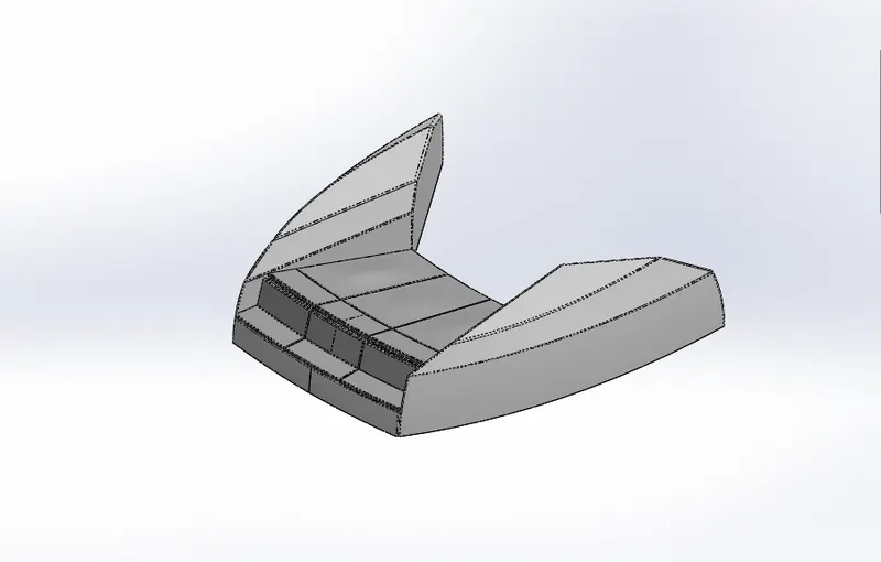
This part is created in a similar manner as the hull. We insert the surface body of the hull. We are going to first make one half of the seat across the mid-plane and mirror it to give us the whole front seat. We first start by creating the outer curved surfaces of the seat using projected curves and surface sweeps and surface extrudes. Then we use surface trim to trim out all the extra surfaces and use surface fill and surface loft to close the open surfaces and make it a solid body. We then knit all the created surfaces together then we then give the necessary fillets to the body. We then use the revolved boss to create a solid body of circular profile starting from the inner surface of the outer body created and use cut extrude to cut excess revolved material to make the revolved boss intersect with the mid-plane. The next step is to use cut extrude thin to separate the outer body from the inner revolve and then create the seats over the revolved boss. We then mirror all the solid bodies created across the mid-plane and give all the details like necessary fillets and chamfer. We combine all the bodies created and finally give the body the appropriate materials and appearances.
Middle Seat
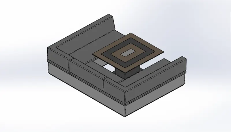
This middle seat is also created in a similar to the front seat. We insert the surface body of the hull. We first make one half across the midplane then mirror the entire body to get the whole middle seat. We first start by making an extruded boss for the base of the seats from the surface of the hull. Then create another extruded boss which will be the body of the seats. We then extrude all the cushions and give the necessary details like fillets and chamfer to the created body. We then mirror the entire body created across the mid-plane and get the whole middle seats solid body. The next step is creating the table. We create multiple extruded boss of the required dimensions of the table and then perform a cut extrude on top of the tables surface for the required pattern. We finish this model by adding the appropriate appearances and colors to the body, cushion and the table.
Rear Seats
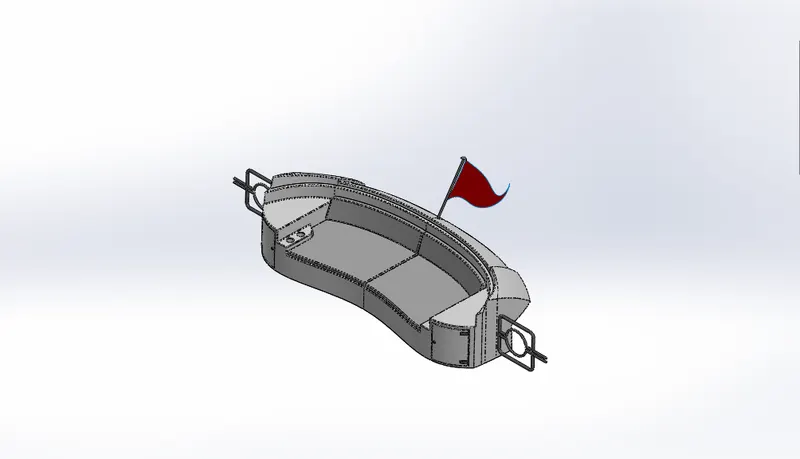
This part is also created in a similar manner to the hull. We insert the surface body of the hull. We first create one half of the rear seats and mirror it across the mid-plane to get our whole rear seat. We start by creating a swept surface for the outer body of the rear seats. we then offset this surface to create more geometry. We trim the outer surface and inner surface to get the desired shape and start using ruled surface to fill the empty spaces between the two surfaces. The next step is to close all the open surfaces which is done by using surface sweep to join all the open edges of both the surfaces on the inside of the seats. The next step is to trim all the excess material and knit all the surfaces created together. We then create surface extrudes to continue closing all the open surfaces and knitting all the closed surfaces together. We then use surface loft to close the bottom and the backside of the two open surfaces then knit everything together. After all the open surfaces are closed and knit together we make it a solid body and start adding details on the rear seats. we first extrude the seat cushions and give he necessary fillets and chamfer all around the solid bodies. We make details on the front side of the seat body and create a small extrude which will be the lights on the backside of the seat. We also create an extrude and make two holes on them to create the cup holders on the rear seats. The next step was to create the gates using swept boss which are connected to the rear seats. These gates are located at the beginning of the stairs. After we have created all the necessary solid body geometry we mirror all the solid bodies across the mid-plane and get our completed rear seats. The last step is to make the flag pole which is just a revolved boss with fillets and finally we create 3D sketches and make a the surface of the flag. We finally give all the appropriate colors and appearances to the rear seat.
Garage door
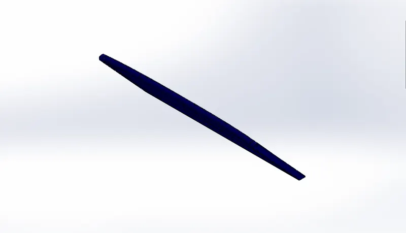
We make this from the saved part we removed from the body of the hull. We start by using the extruded cut to remove the whole backside of the solid body to just retain the front part of the desired thickness. The next step is to shell the inner surface of the garage door and applying the necessary fillets on the inside.and outside. Next step was to make a cut extrude to make the hole which is going to be used in the opening mechanism when the door is attached to the hull. We add more details to the body like fillets and then mirror the entire body across the mid-plane to finish the entire body ofthe garage door. Last step is to create an extruded cut an add the necessary text and then we add the appearances.
Superstructure
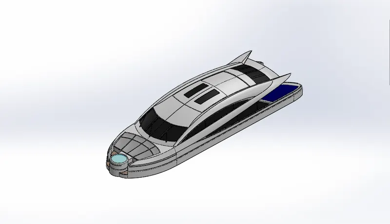
We insert the surface body of the hull. Then we are going to model this part similar to the hull by first creating one half and mirroring it across the mid-plane. We first create a surface extrude in the shape of the superstructure and a swept surface and trim the extra surfaces and knit them together. Then we create a ruled surface tapered inward as we are creating the rest of the surface bodies upwards. Then we make two projected curves then create a lofted surface of the desired shape of the superstructure and trim the extra surfaces. We then create a swept surface between the two created surfaces and perform surface trim to remove all the extra material, these are the windows on the lower mid portion of the superstructure. We then knit all these surfaces together. We then create another surface loft for the upper surface of the superstructure all using projected curves. We knit all the created surfaces together before moving on. The next step is to create the windows of the superstructure which is done by using the rules surface option.and then we trim all the extra surfaces and knit them together. We then use lofted surface, extended surface and trim surface to close all the open surfaces to create a closed surface geometry. Once we have made the overall side structure of the superstructure we can move on to making the back doors by using extruded surface option and knitting all the bodies together. Using the extruded surface, extend surface and trim surface options we continue creating the details on the front and back portion of the superstructure, and knit all the surfaces together once they are all closed. The next step is to create the swept surfaces for the cushions on the front side of the superstructure. Then use extruded boss to create the cushions. The next step is to make the Jacuzzi. We make an extruded boss and create a cut extrude for the required geometry and then cut the jacuzzi in half and make it a surface body. We also make the stairs leading to the jacuzzi. Finally we add more details all around the superstructure windows and create the windshield with all the necessary details. After all the details have been applied we can kint all the surfaces together and make it a solid body. Now we have applied everything to one half and we can mirror the half across the midplane and we have the entire superstructure. Last step is to create the wipers for the windshield of the superstructure and then apply all the appropriate appearances and colors to the superstructure.
Radarmast
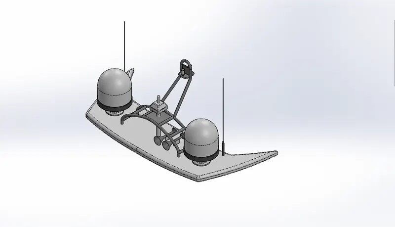
We create this part also similar to the hull by first creating one half and then mirroring it across the mid-plane. We first start by creating the base of the Radarmast using the extruded boss and applying all the necessary fillets around this extrude. The next step is to create a revolved boss for making the lights and applying the necessary fillets. We then create the antenna by using boss extrudes and applying the necessary fillets. Next step is to use swept boss to create the frame supporting the mid-portion which is going to hold the radar. Then we use boss extrude to create the central piece which will hold the radar. We then apply all the necessary fillets and chamfer to the body. The next step is to create a revolve for the light which is fixed on the top portion of the frame and mirroring the light on the back side of the frame. We then create a revolved boss for making the horn/speaker and mirror this body right next to the first one. After applying all the necessary fillets and chamfer, we can mirror all the parts across the mid-plane and this gives us the completed radarmast. Last step is to apply the appearances and colors.
- Assembly
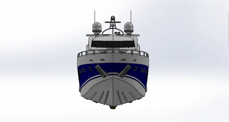
Front View
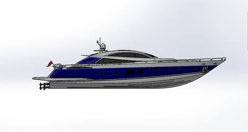
Left side view
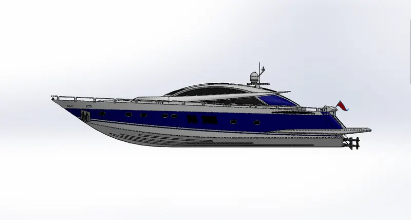
Right side view
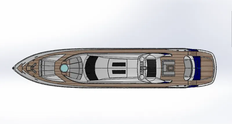
Top View
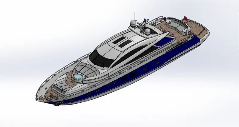
Isometric View
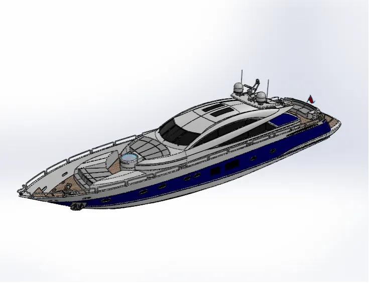
Camera setup View
- Renders
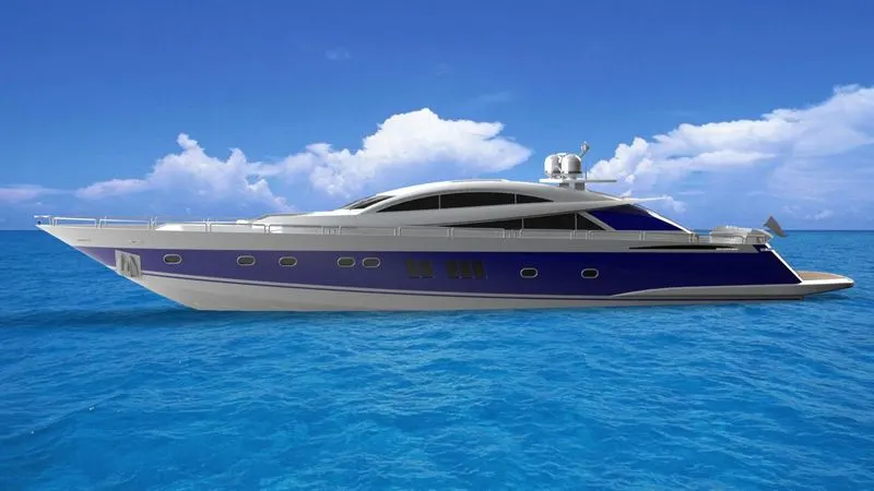
Side View
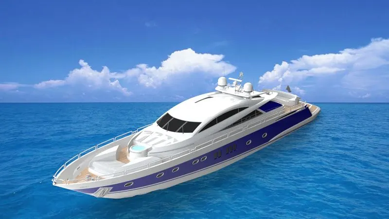
Isometric View
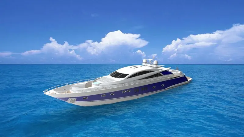
Camera setup View
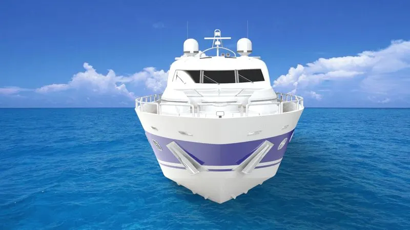
Front View
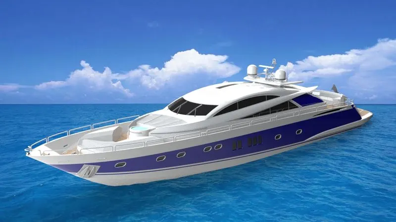
Final Render
Photoview 360 Render
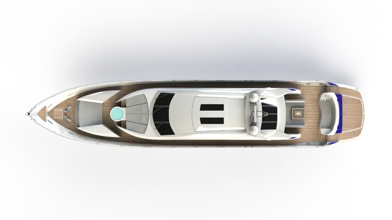
Top view
- Conclusion
This was the second project I worked on with solidworks 2019. I learnt a lot of new features during the course of designing the predator yacht. This body taught me surface modelling which helps us design complicated curves and surfaces and helps us convert it into a solid body. It was a wonderful experience working on this project and skill lync gave me a great platform to learn a lot of new skills in the duration of this ultimate solidworks course.