Photo Realistic Rendering
Designing and Assembly of the American Chopper
- ObjectiveThe objective given to me was the designing and assembly of the American This includes designing the following parts - Transmission belt, kickstand, front fender, Rear fender, Chain, Oil tank, pedal, front wheel, rear wheel, front fork, chassis, engine and the gas tank. Then assembling these mentioned parts to create the final assembly of the Americanchopper model. Then render the assembly with the required views.
-
Introduction
The designing of an American chopper started with the creation of each part individually using a software called Solidworks 2019. The first part created was the transmission belt followed by the kickstand, front fender, read fender, chain, oil tank, pedal, front wheel, rear wheel, front fork, chassis, engine and the gastank. These parts were first designed with the appropriate features and appearance(material) then assembled into one assembly which helped us finish the complete model of the American chopper motorcycle. This assembly was then rendered for a photo-realistic view in the appropriate environment. I learnt a lot doing this project in using the software Solidworks 2019 and also all the capability it has in creating complicated parts and assemblies. I have further explained the creation process in this report.
-
Design Methodology
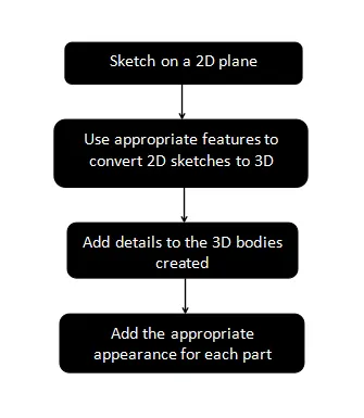
- Description
Sketches
The first step in designing is creating the appropriate sketches on a 2D plane with the necessary dimensions and constraints. We must fully define the sketches that are created to move forward to the next step. I learnt to use a lot of new sketch tools ranging from basic tools like lines, arcs, circles, rectangles etc to complex curves like splines and projected curves. A projected curve is sketching on two separate 2D planes to create a sketch which exists in the 3D quadrants which can be used to design complicated geometry, for example I had to use projected curves to design the exhaust pipes coming from both the cylinders of the engine.
Features
The next step in designing is to make the sketches on the 2D planes come out into the 3D. This is done by using features like extrude, revolve, extruded boss, etc. These features make fully defined closed sketches come out of the plane giving us solid body geometry in 3 dimensions. Some other features I used were shell which can make a solid body hollow, fillet command which helps us give a smooth rounded finish on sharp edges, chamfer command which helps us chamfer the sharp edges of the solid bodies. Extruded cut and revolved cut helps us in removing excess material from out solid bodies which is also done by creating sketches on the 2D plane and then using these sketches to remove the material. another very useful command which was used a lot in designing the chopper was the linear pattern and circular pattern. these help us replicating the same geometry that has been created once on the solid body n-number of times in a linear or circular path.
Appearance
The next step after we create the perfect solid body is to give these solid bodies their materials and appearances. we have a wide variety of materials to choose from on solidworks 2019. We must give the appropriate materials to the parts for it to look realistic. We can also give these materials we choose colors of our choice.
Assembly
The next step after we have modeled all the parts is to import all these files into a new assembly. In this new assembly we fix the frame or the chassis and then bring in all the parts to be fixed onto it one by one and constrain them onto the chassis and merge them all into one body. Once we have our complete assembly we can make any corrections if necessary or we can move on to the next step.
Render
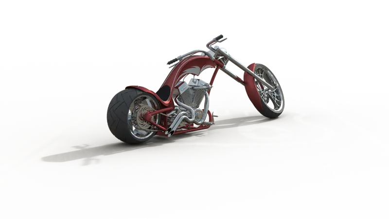
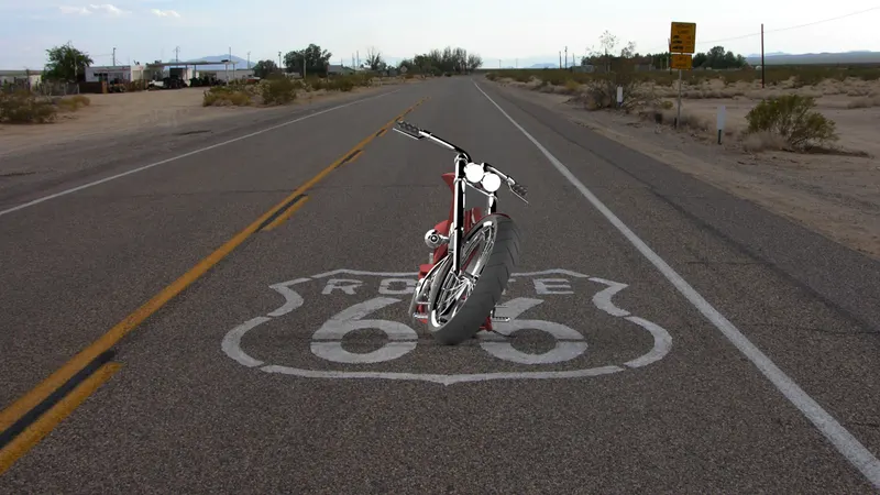
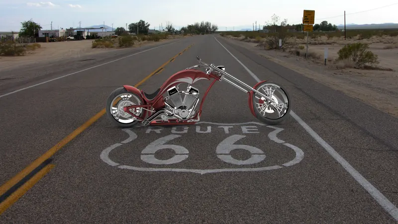
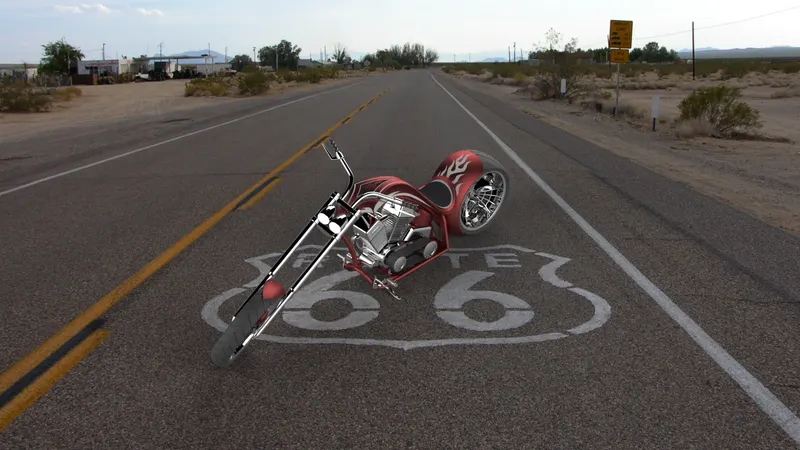
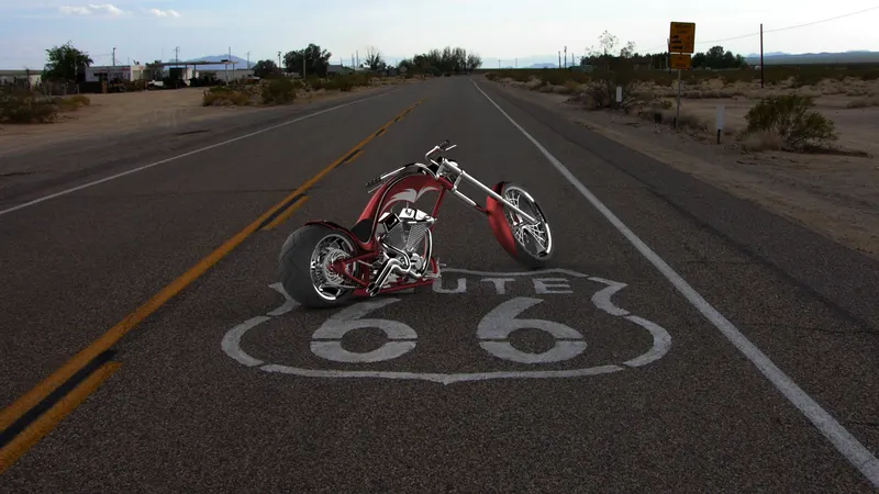
This is the last step where we use photoview 360 which is an inbuilt rendering tool in Solidworks 2019 to make our Assembly look as realistic as possible. Rendering basically makes the materials look how they do in real life by giving them their physical properties. Another Rendering software I used to finish the final render was Solidworks visualize. This software helps us add a lot more appearance to the model and also lets us place out assembly in the appropriate environment or scene. This gives us a realistic feel.
Parts modeled with a brief about their features.
Transmission belt
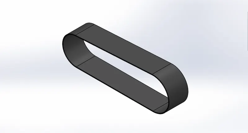
This is a very simple part which was made by creating a sketch of that shape on the front plane and then extruding it to the necessary width. then I used fillets to smooth-en the edges and added a rubberized material for the appearance which gave us this transmission belt. Finally we add the appearance.
Kickstand
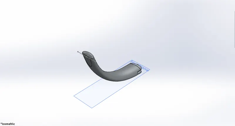
This kickstand was created by using a guided curve in this case a spline which gave us its shape. The feature we used to create this was a lofted boss which gave us a tapered look of its elliptical shape. Then we added some domes and created cuts which will allow it to be fit onto the chopper. Last step was to add appearance.
Front fender
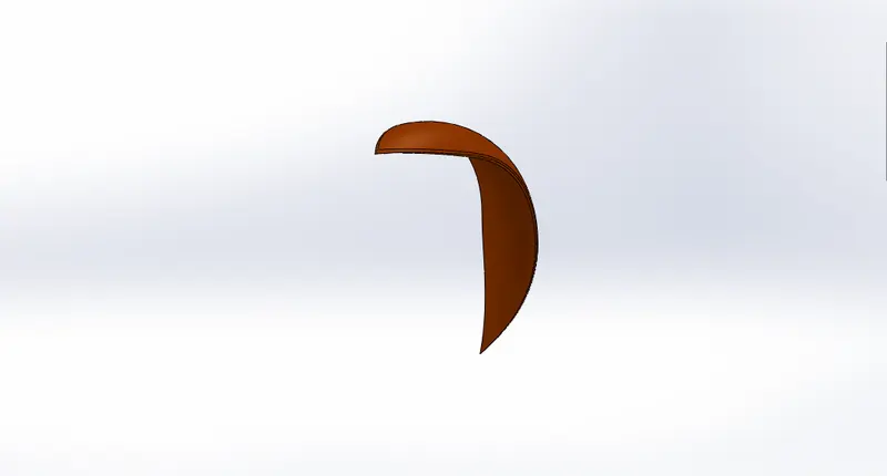
This is the front fender which was created by sketching a closed curve on the plane and revolving it to get a solid body. the we created a sketch to give it the shape and used the split tool to remove excess material to get the sharp edges on the fender. we then use fillets to smooth-en the sharp edges around the fender. Finally we add the appearance.
Rear fender
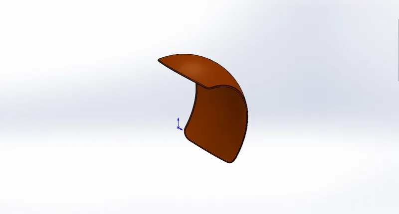
This rear fender was created following the same steps as the front fender but only thing that is different was the thickness and width of the revolve. Then we added the appearance.
Chain
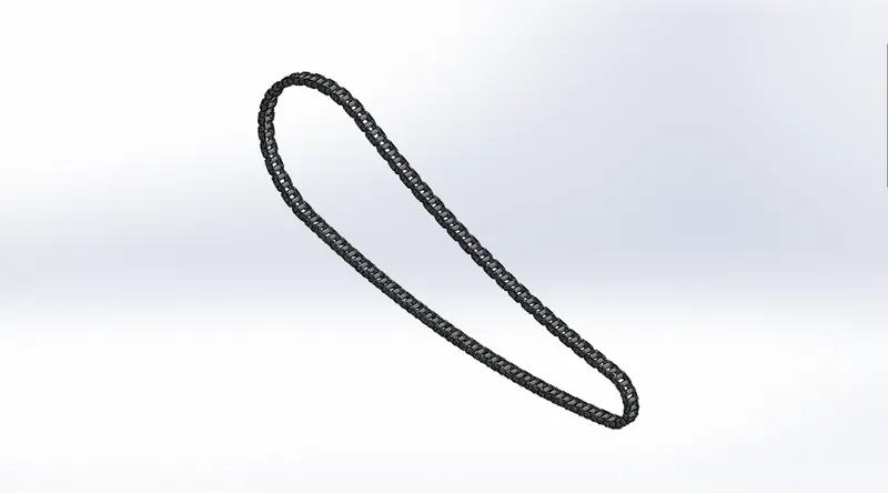
This part was a little tedious to model. First we sketched the outer plate and the inner plate of the chain on the midplane and created two extruded links. Then we made these plates with their connecting rods into blocks. We then manually connect these blocks to each other and pattern them around the chain shaped sketch and finally mirror the plates across the midplane which gave us the completed part. Then we add the appearance.
Oil tank
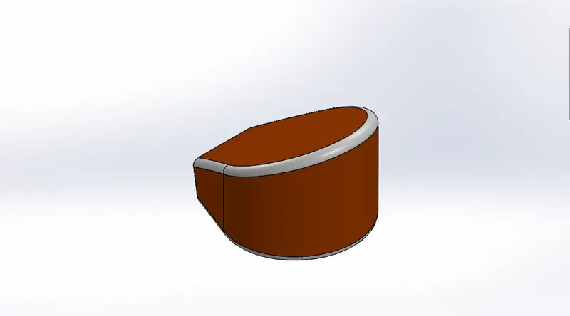
This model was made by creating two extrudes, first from the top plane giving its shape from the top and the second extrude from the front plane. Then we used the combine feature and used the common part extruded to get our desired solid geometry. Then we used fillets to round all the edges and then used the shell command to make the oil tank hollow. Finally we added appearance.
Pedal
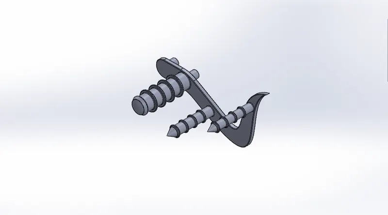
First we create the base-plate for the pedal by creating a sketch and extruding it. then we created a revolved extrude for the part where we rest our heel. Then we created all the circular profiles and extruded them and added circular ridges over all the cylindrical profiles where the foot rests and did a linear pattern to replicate the ridge. This was done for grip. And then added all the necessary fillets and chamfers and finally added the appropriate appearance.
Front wheel
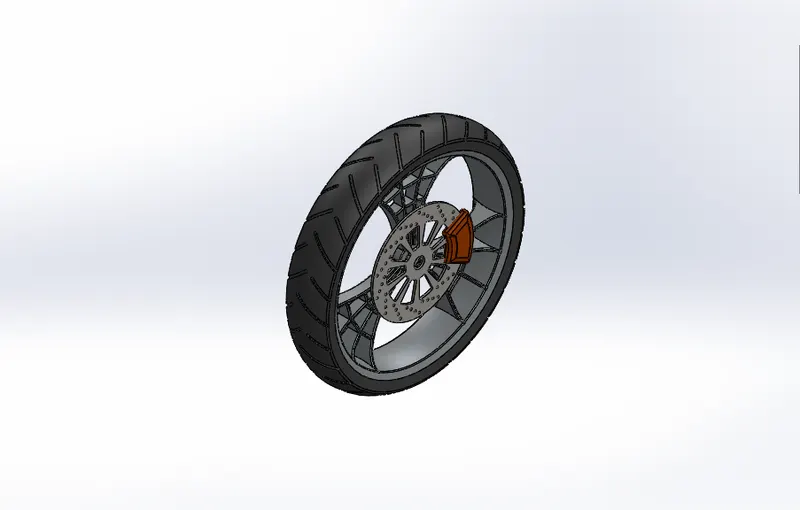
We first start by creating a sketch on the front plane and revolving it to make the rim of the wheel. Then we want to make the spiderweb pattern for which we extrude a sketch from the right plane and create the spiderweb design and extrude cut it. Then we use the circular pattern to pattern the spiderweb pattern on the rim. Then we do a revolved cut to give a concave face on both sides of the rim. We then combine all the created parts and then extrude the disc brakes. And make the necessary patterns around the disc. Then we make the brake calipers. Next step was to make a revolved extrude for the tyre. And give the grooves on the tyre by using extruded cut and circular pattern. Finally we add all the appearances to the parts of the front wheel and combine them all together and give the necessary fillets on the sharp edges.
Rear wheel
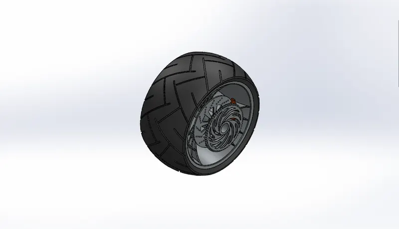
All the steps till are same as the front wheel except the width of the rim is a lot more and we make a rotor and calliper same as the front tyre but also create a sprocket in this part around which the chain will rest. Finally add all the appearances.
Front fork
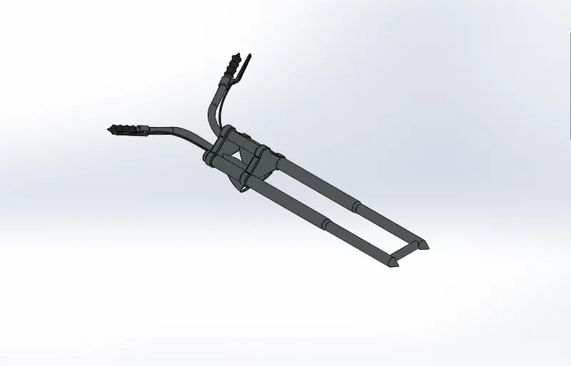
We first start by creating a sketch for a revolve on the front plane and make one of the fork tubes. Then we make the triple clamps on on the top surface of the revolve we created and use linear pattern and join the two triple clamps. Then we revolve the headlights and make the axel. Then we use the projected curves option after creating two sketches on the front and top plane to make a path for our handle bar. Then we use extruded boss and use the projected curve as our path to create the handle bar. Once we create the handlebar, we create new reference planes to create the grip and the brakes. Finally we create brake wires going from the handle bar and mirror all the components we created across a new reference plane created exactly in the middle. Then we combine the two mirrored bodies. Finally we add the appropriate appearance and give more detailing to the headlights created.
Chassis
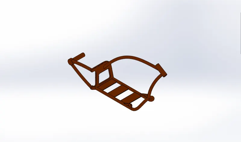
For creating the chassis, we first import an sketch image of the American chopper and place it on the midplane for reference. We then start by making two sketches on the midplane and the bottom-plane for creating a projected curve. Once we create the first projected curve we have a bath to create the base on one side of the chassis. We use extruded boss and create the base on one side. We then mirror this base created across the midplane. We have the bottom tubing now. Then we extrude the back-plate from which we are going to create the rods holding the back axel. Then we move on to creating the rod on which the gas tank is going to rest and another extrude which is going to connect to the gas-tank rod and we make a hollow revolve which is going to give us the location of our handle bar triple clamp to be fixed. We then create three plates to fix the engine on which is attached to the mirrored base rods of the chassis. Once we do this we create side plates to attach the pedals and a small extrude to pivot the kickstand.. finally we place all our fillets and chamfers and give the appropriate appearances.
Engine
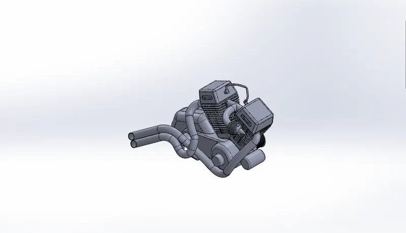
This was the most complicated part to create. First we imported the sketch image of the chopper for our reference. The next step was to make the base of the motor which is done by creating a sketch on the midplane and then extruding it to make the necessary shape and adding the details on the motor by making all the extrudes on the outer surface. Then we create the back half in a similar manner and merge it to the base of motor. We then apply fillets to the motor created. Then the next step is to create the front and back pulley connected to the motors onto which the transmission belt will be fixed. We create circular patterns on both the pulleys to give it the ridges needed to hold onto the transmission belt, then added more details to the pulleys. Then we create the geometry for the starter motor and combine it to the rest of the engine. The next step was to create the cylinders which is extruded from a new reference plane created at the appropriate angle normal to a reference line from the motor. We then make a square extrude with a draft to make the cylinder, and another extrude connecting it to the motor. The next step was to make the top section of the cylinder and giving it a chamfer and adding details to the top section and create a spark plug from the top section. Next we create a cutout for the cooling fins and give it fillets to smooth the edges. We then create a linear pattern and complete the model of one cylinder. Next we create and mirror the first cylinder onto the motor using the right plane as reference and combine all the bodies. Then we made the four legs for the engine which is going to be attached onto the chassis. Then we create the sprocket with teeth to attach the chain onto. Then we make a tube connecting the two cylinders and create an intake valve which is connected to this middle tube. The next step is to make the exhaust pipes coming out of both the cylinders. We make projected curves and composite curves for the path of the exhaust pipes and then extrude the two hollow tubes out of both the cylinders and create the exhaust pipes. Finally make spark plug wires connected to the spark plug. Then combine all the created parts and add the appropriate appearances.
Gas Tank
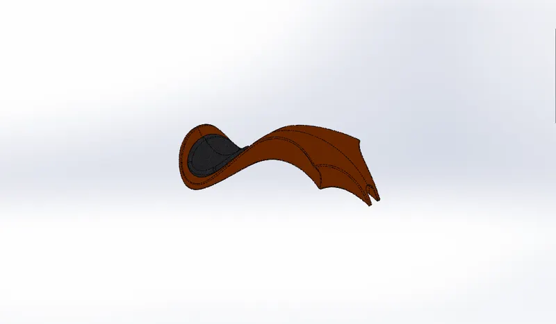
We start by importing the sketch image for a reference. Then we start by creating sketches on two planes to make a surface sweep for one side of the gas tank. After we have created the basic sweep we then use the surface trim option to trim the surface according to the required shape. We then make a projected curve to form the side profiles of the gas tank. Once the curve is created we can use the lofted surface option to create the side-front of the gas tank and finally finish the side of the gas tank using the boundary surface option and finish the side-back profile of the gas tank. The next step is to mirror the created geometry and knit the two surfaces created. Then we create a surface extrude to create the seat on the gas tank. We then close the bottom using the boundary surface and make a swept cut to create a gap to fix the gas tank onto the chassis. Then we knit all the surfaces together again and add the necessary fillets around the part. Then the last step is to add all the appearances.
5. Assembly
Front View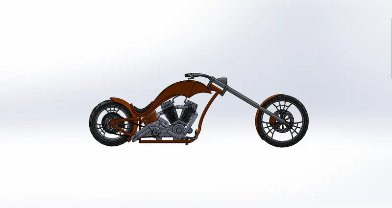
Top View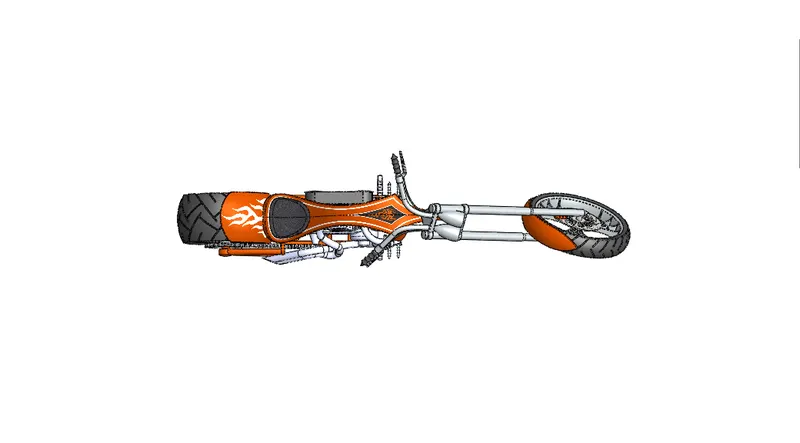
Left side View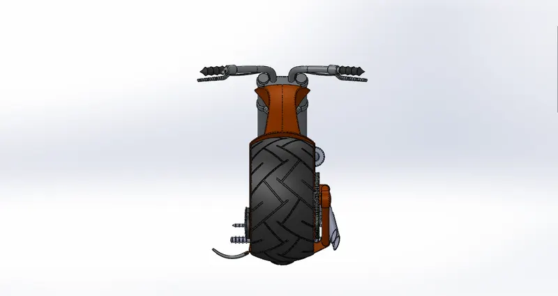
Right side View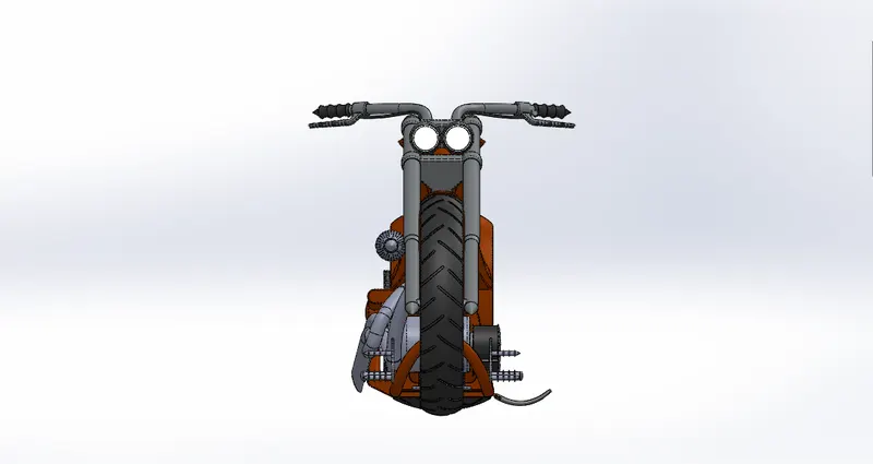
Isometric View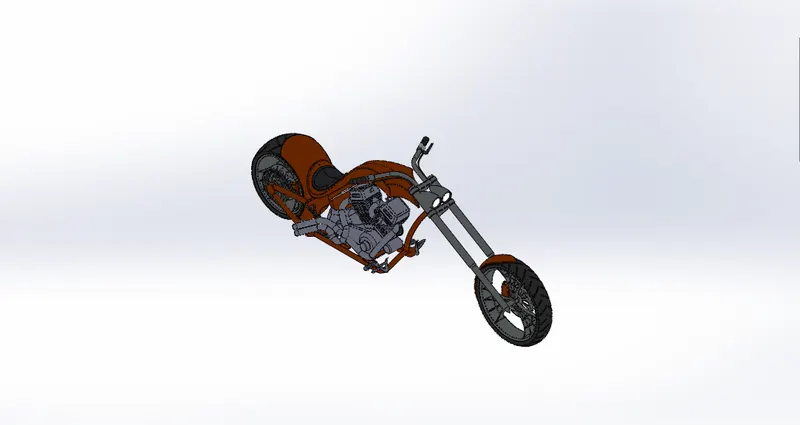
Camera setup View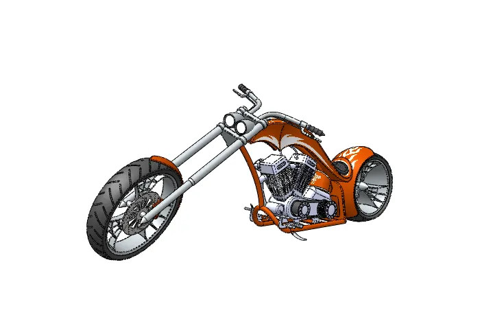
6. Renders
Photoview 360 render
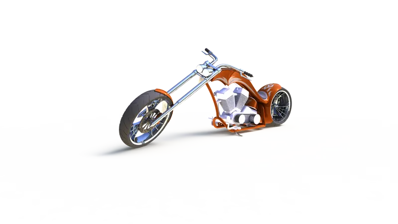
Renders made with Solidworks Visualize
7. Conclusion
This project helped me learn from the basics about how to design and create 3D parts, assemblies and renders using Solidworks 2019. It has been a wonderful learning experience and making this project report made me realize all the things I learnt since I started working on this model. Skill-Lync has offered me a great learning platform and I hope I have done well in making all the parts and assemblies.