Week 8 - Challenge 2 - Base Bracket Design
Report on Tooling axis creation.
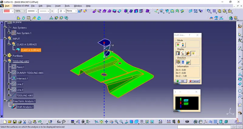
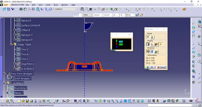
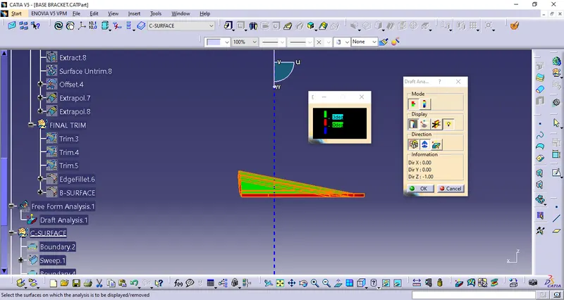
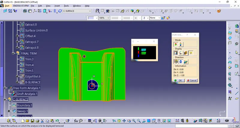
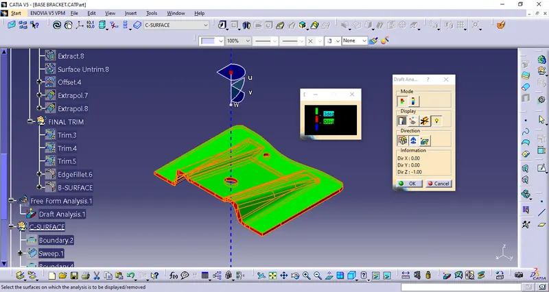
We first observe the class A surface given to us and we see two holes present in the base bracket surface. We choose the hole towards the centre of the class A surface. We then insert a point at the centre of this hole and create a line passing through this point across the Z-axis. We name this line as DUMMY TOOLING AXIS. We then insert an axis system at the point created and we use intersection tool with the ZY plane and the class A surface. This gives us the intersection profile. We create two point-point lines on the two angled profiles on either sides and extend these lines. The next step is to create a bisecting line using the two extended lines created on either side. This is our main TOOLING AXIS. We change the color f this axis and our Class A surface is ready for draft analysis. We open Draft analysis and click on the surface of the component, then place our compass on the TOOLING AXIS and check for any issues. Once this is completed we have the Draft analysis of our Class A surface. After making the Class A, Class B and Class C surfaces, we create a closed solid body and perform draft analysis on the completed plastic part and check for any issues.