Week 8 - Challenge 3 - Switch Bezel Design
Report on creation of tooling axis and draft analysis.
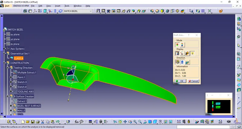
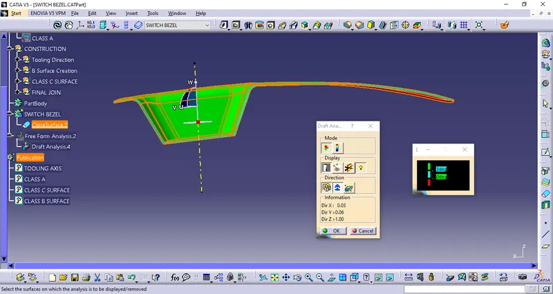
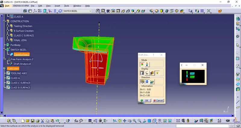
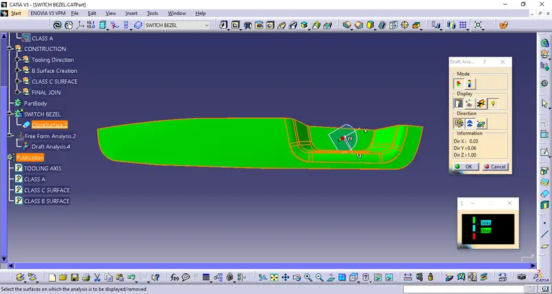
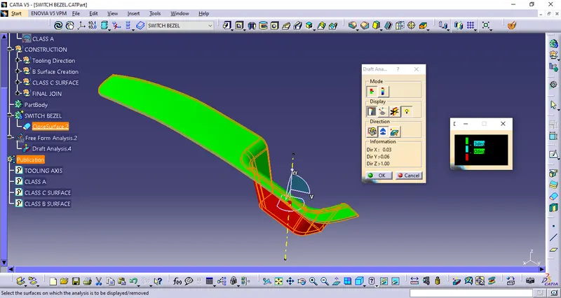
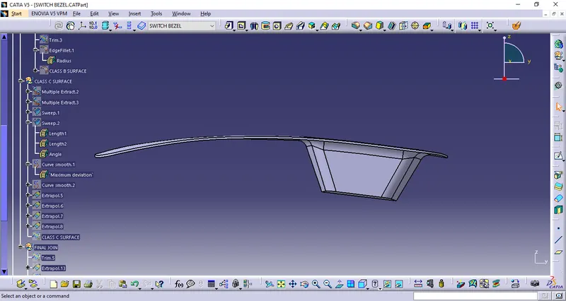
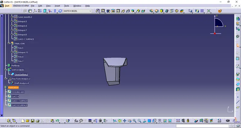
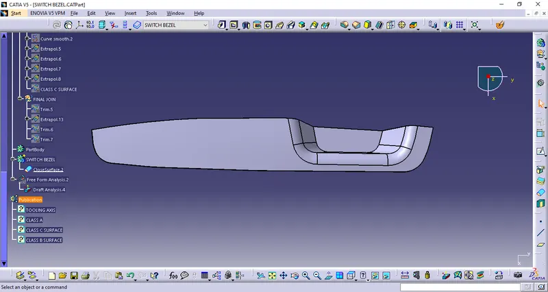
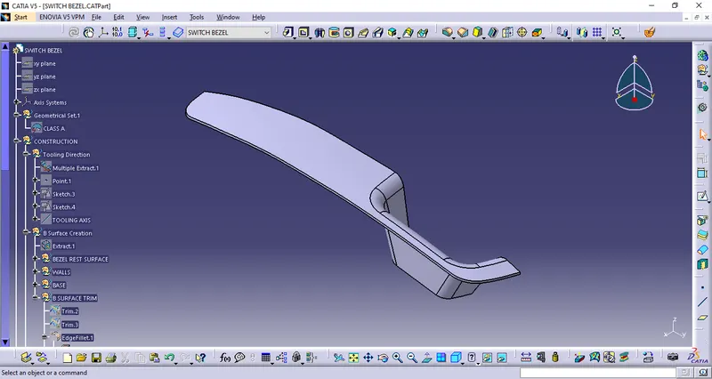
We first recieve our class A surface annd observe it. We see mainly three surfaces with drafts which is the handle portion. We start by creating a point at the centre of the base surface of the gap and place an axis system on this point. After doing this we create a new sketch across the YZ axis of the newely created axis system and we project 3D elements of the class A surface. We then draw two lines on the angles surfaces profile and create a bisecting line in 3D and turn all other elements of the sketch to construction. We have the tooling axis across Y direction now. The next step is to create a tooling axis along the X direction. We start a sketch on the XZ plane of out axis system and intersect 3D elements but there is only one angled surface on which we draw a line and then we create a line from the point we created on the base extending out and give an angle of 5 degrees between these two lines created in the sketch and make all other elements other than this 5 degree line construction elements. This gives us the tooling axis across X direction. Now with these two lines that we have created across X and Y direction, We create another bisecting line bisecting these two lines. This bisecting line that we create is going to be our main tooling axis. We can now Perform our draft analysis on this surface. We go to insert, Analysis, Feature draft analysis and click on the surface of the Class A surface or the plastic component and place the compass over the tooling axis and check the manufacturability of the design.