Week 8 - Challenge 2 - Base Bracket Design
REPORT
Objective: The aim to create the base bracket from Class-A surface of the base bracket by creating tooling axis, Class-B surface, Class-C surface and performing the draft analysis on the base bracket component to confirm the eligibility of the design of the component whether it will easily go through the manufacture process.
Draft Analysis is performed on the component to check the tooling axis and the parallel surface if they are insecting or not, which helps to remove the component from core and cavity in the manufactiring process.
Tooling Axis Creation
This is the axis in which the component is removed from the core and cavity in production process.
- For creation of tooling axis, we need to visually identify the tooling direction of the component.
- Boundary or join commands can be used to see the continuity of the surface.
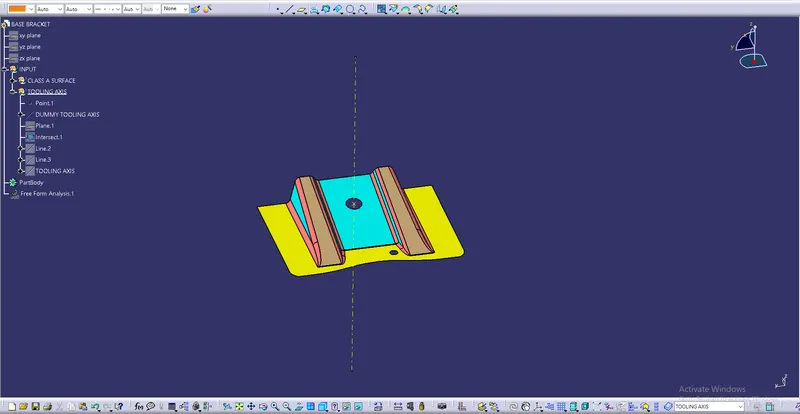
- Extract the boundary of the surface and intersect the lines, In this a plane was used for intersection.
- Surface lines was created with the point to point line to see the clearence of the line intersection.
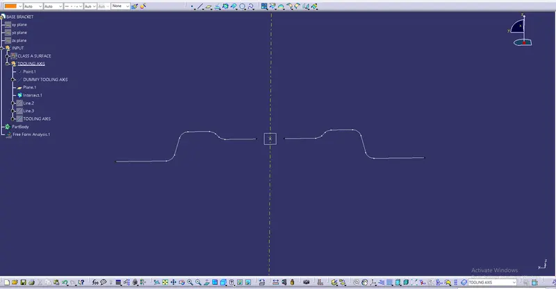
- Then create the dummy tooling axis with the point and direction method in the suitable direction.
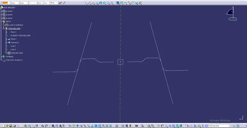
- In this component the suitable tooling direction was Z-Direction.
BISECTING METHOD
To see clearance of the tooling axis with the surface draft, we create surface lines and bisect the surface lines with the dummy tooling axis to get the final tooling axis.
The steps we follow in this process:
- First we create dummy tooling axis.
- Then the intersection of surface is done.
- The surface lines is created with point to point method, the intersection of the surface lines which are parallel to the tooling axis is checked in this process.
- Then the surface lines and dummy tooling axis is bisecting to form the real tooling axis.
DRAFT ANALYSIS
The draft analysis of the base bracket was performed in the way explained below:
- The initial step to convert the view mode into the material mode.
- Then insert the feature draft analysis
- Click on the compass and align the compass with the tooling axis
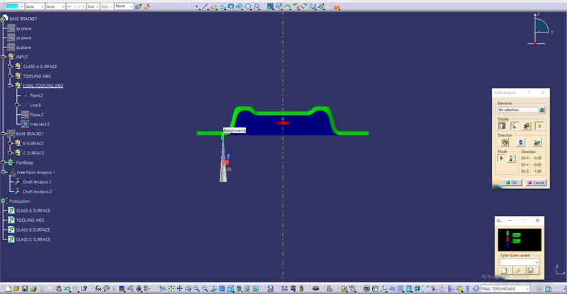
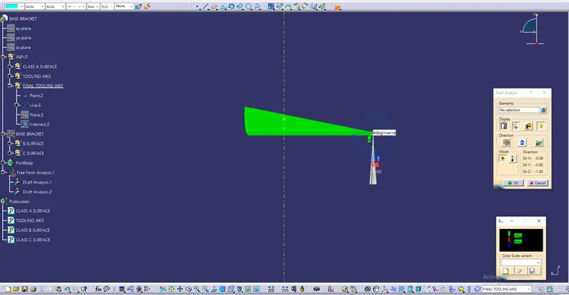
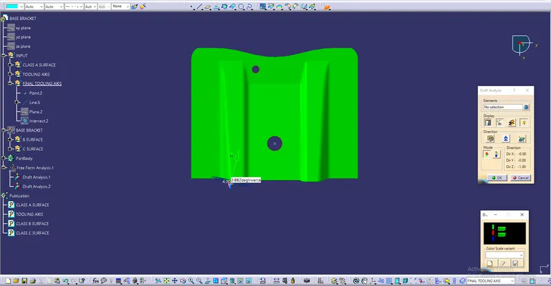
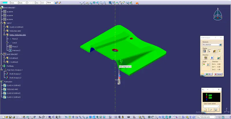
- Then the feature analysis under the point is used to see the draft angle of the surface.
PUBLICATION
This publication feature is used for creating a shortcut for the features from the feature tree for easy access.
In this the publication of Class-A surface, Class-B surface, Class-C surface and Tooling axis is done.
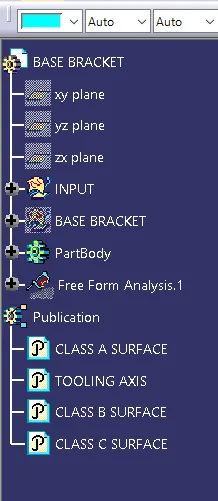
Draft Analysis of the base bracket solid part
Front View
Side View
Top View
Isometric View
Conclusion
Draft Analysis was performed in Catia V5 software to check the draft provided to part model for easy manufacturing process.