Photo Realistic Rendering
American Chopper By Gaurav Sharma
The Purpose to design this chopper was to explore the tools that are used for designing in the Solidworks and going through the sketching, dimensioning, part modeling, assembling, rendering to create a somehow real design for the real world.
This Project contains demonstration of American Chopper's entire Sketching, Dimensioning, part modeling, assembling and rendering for real visualization in a sequential manner.
The American Chopper Consists of Parts Mentioned Below:
1. Transmission Belt
2. Kick Stand
3. Front Fender
4. Rear Fender
5. Chain
6. Oil Tank
7. Pedal
8. Front Wheel
9. Rear Wheel
10. Front Fork
11. Chassis
12. Engine
13. Gas Tank
The American Chopper's Parts Description and Tools used in the modelling:
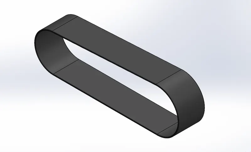
1. Transmission Belt: The belt which is used to transmit the power from the Engine further to the Gear box is simply known as Transmission Belt. Initially it was sketched on the Front plane and after that dimesion and relation were given, offset tool was used here to copy the sketch outside and it was extruded and filet was added to the edges to form the final shape of Belt. Ultimately the appearence of Rubber material is added to the transmission Belt.
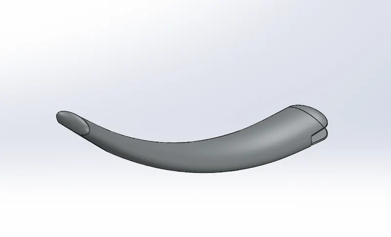
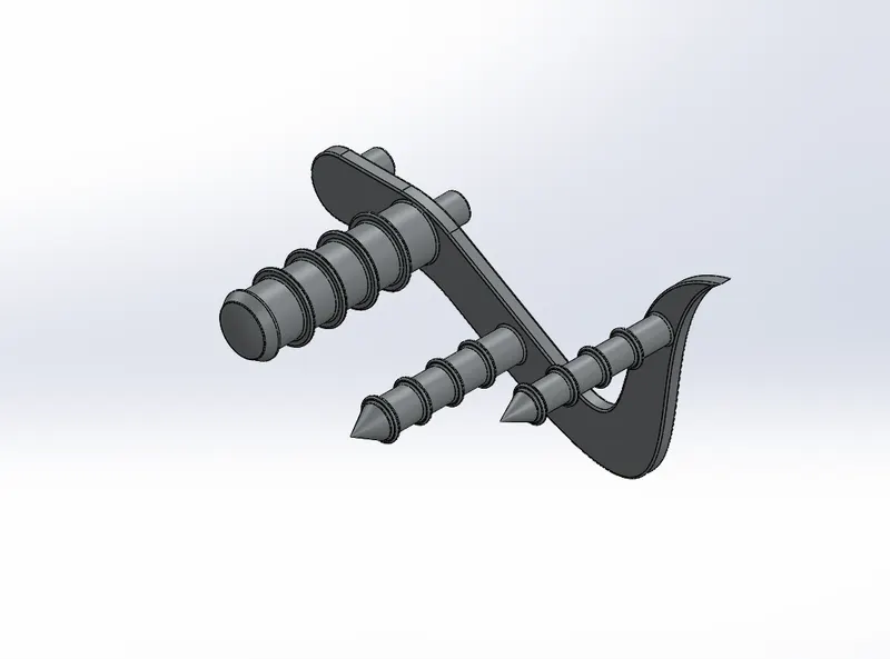
2. Kick Stand: The kick stand is used to provide a support for the two wheel vehicles to stand in a stationary vertical Position.
The sketch includes two ellipses on the right plane and another plane at different postions and connected by a spline on the front plane by the Pierce relation. The major tool used here after sketching and dimensioning was lofted boss/base and dome was used to provide the curve or round forming shape to the ends of kick stand. Then the extruded cut and extruded boss/base was used and filet was applied to the edges. The Split feature was used to give a flat shape to the bottom of the Kick stand. Appearence of steel was added to the part for realistic appearence.
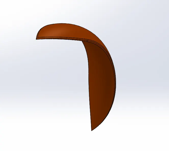
3. Front Fender: The front fender is used to protect the Dirt and other particles that can reach the rider or the vehicle itself while the wheels are in motion.
The front fender was sketched and revolved around a axis in two direction with different dimension. The other tools are used here three point arc, offset, trim entities, split, shell and fillet.
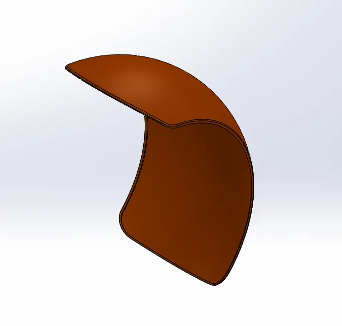
4. Rear Fender: The Rear Fender also serves the same purpose as the front fender but on the rear wheel.
The Rear fender was sketched and revolved boss/base feature was used to form the shape and other tools used here were offset, trim entities, fillet. Appearence was also added to the part.
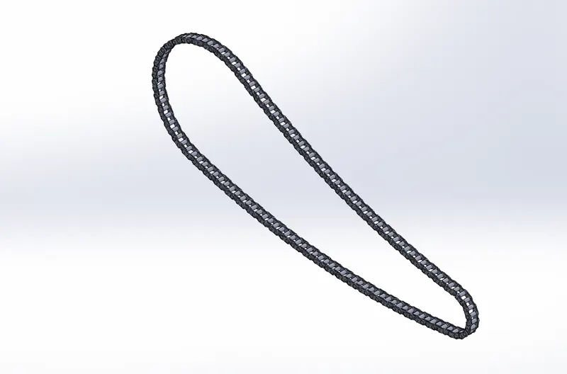
5. Chain: Chain is used to transmit the rotating motion from one sprocket to another sprocket, that to mainly give motion from the gear box to the wheel which is connected through shaft and sprocket.
The chain concludes of a same small parts that we have used to make a complete part. The block was made to use the same entity again to make the complete geometry. The another great feature used here was Curve Driven pattern to create the geometry already created and that means using that same geometry to create further.
6. Oil Tank: The oil tank is a closed shape container. The Oil tank's purpose is to store the oil which is used by the engine.
The oil tank was sketched and mirrored by the axis. Extruded boss/base feature was used to make it into 3d object. Then the another shape was sketched on the shape then the feature called combine was used to convert two different shapes into the one sum of the two shapes. Finally the shell feature was to make the hollow shape of the tank, fillet was applied and appearences were given to the part.
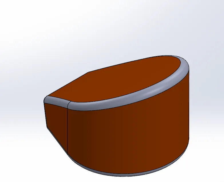
7. Pedal: The pedal is a small and important part which is connected with the chassis to provide rest to the rider's foot and the positioning of the pedal occurs where the foot brake and gear changing shaft or module is available.
The pedal was sketched and dimension were given, the feature that it includes are extruded boss/base, extruded cut, Dome, Fillet, Chamfer, then the final appearences were given to the part.
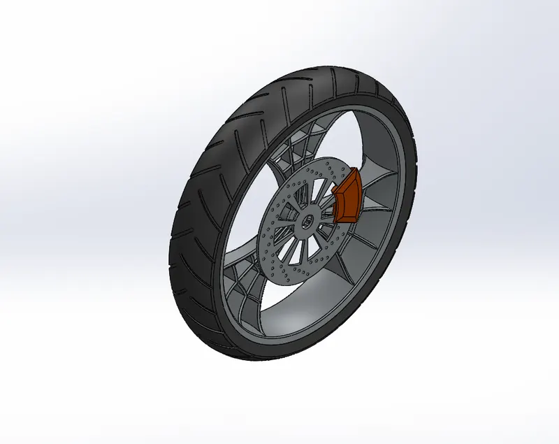
8. Front Wheel: The front wheel provides direction to the vehicle by the command given on the front fork and moves the vehicle by rolling over the road surface. The Front wheel also contains some important parts like brake caliper and rotor.
Front rim was sketched and revolved over the centerline and then the tire was extruded on the rim. The Feature that are used to make the front wheels are:
Revolved Boss/Base
Revolved Cut
Extrude Boss/base
Extrude Cut
Trim Entities
Linear Pattern
Circular pattern
Fillet
Appearences
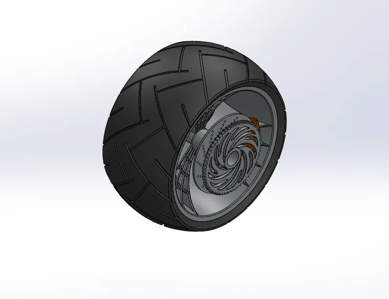
9. Rear wheel: The rear wheel is the circular shape driven wheel in the assembly, that moves with the motion of the sprocket connected to the chain which gives the motion to the whole body of the assembly to roll over the surface.
The disc caliper, rotor and sprocket is also attached to the rim of the rear wheel.
The Rear wheel rim was sketched and revolved around the axis and then tire was also revolved around the rim. There are many features were used to make the component are:
Revolved Boss/Base
Revolved Cut
Extrude Boss/base
Extrude Cut
Trim Entities
Linear Pattern
Circular pattern
Fillet
Appearences
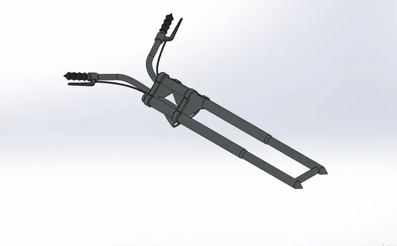
10. Front Fork: The Front fork is individual part with small other component assembly like it controls the front wheel, it contains headlamps bucket and headlamps as well, it also includes the front telescopic suspension and have some wiring cables passing through in it.
The Sketch was drawn and after dimension other tools were used like:
trim entities
Extrude Boss/base
Revolved Boss/base
Extruded Cut
Revolved Cut
Projected Curve
Sweep
Split
Mirror
Dome
Planes
Convert Entities
Move/Copy Body
Appearences
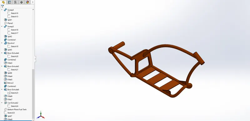
11. Chassis: The Chassis is the frame or skeleton of the bike which carry every part on it. It is a rigid structure with hollow pipes with low weight and strong endurance.
The construction of chassis includes the use of sketch tools and feature tools are mentioned below:
Sketch
Offset
Convert Entities
Trim Entities
Plane
Projected Curve
Revolved Boss/Base
Extruded Cut
Sweep
Split
Fillet
Appearences
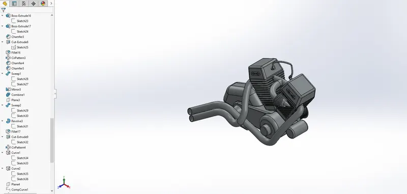
12. Engine: The Engine is the mechanical motor which converts one energy to another energy to final form of mechanical energy to move the vehicle from one place to another. It converts linear motion to rotatry motion to give rotation power to the wheels.
There are number tools are features are used to create the model of the engine are following:
Sketch, Convert Entities,
Offset,
Trim Entities,
revolved boss,
extruded Boss/base,
extruded cut,
Composite curve,
Projected Curve,
Sweep,
Mirror,
Circular pattern,
Split,
Appearences
13. Gas Tank: The gas tank contains and protect the fuel tank from the exposure of the environment which is mandatory because the fuel tank contains the flammable fuel, so the protection of fuel tank by the gas tank is required.
The Tools that are used for construction of Gas tank are:
Sketch
Convert Entities
Trim Entities
Projected Curve
Surface Trim
Surface Knit
Filled Surface
Sweep Surface
Sweep cut
Fillet
Appearences
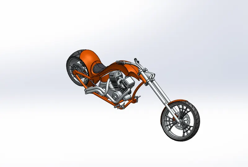
Assembly of The American Chopper
The Assembly of chopper was done by opening the all parts in the assembly window then according to the positioning of parts required mates were applied and those are Coincident, Concentric, Tangent, Distance mates, Plane mates, Angle mates, etc.
|
Assembly Design Tree |
|
TRANSMISSION BELT |
|
KICKSTAND |
|
CHAIN |
|
REAR FENDER |
|
REAR WHEEL |
|
PEDAL |
|
FRONT FENDER |
|
FRONT WHEEL |
|
OIL TANK |
|
FRONT FORK |
|
CHASSIS |
|
ENGINE |
|
FUEL TANK |
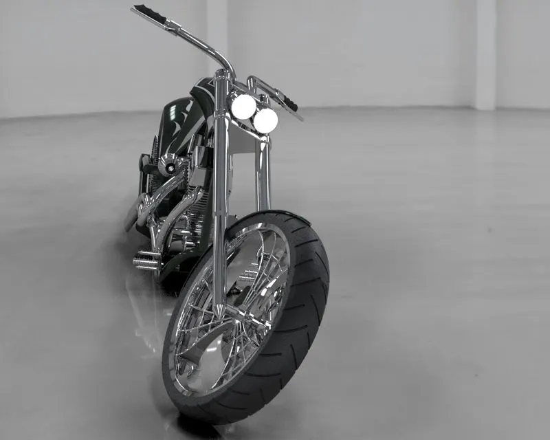
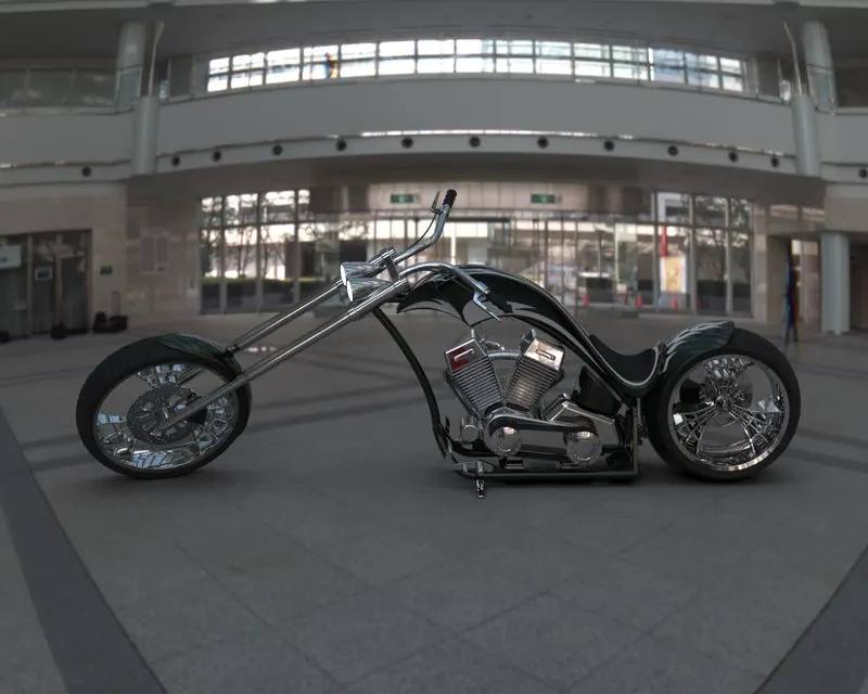
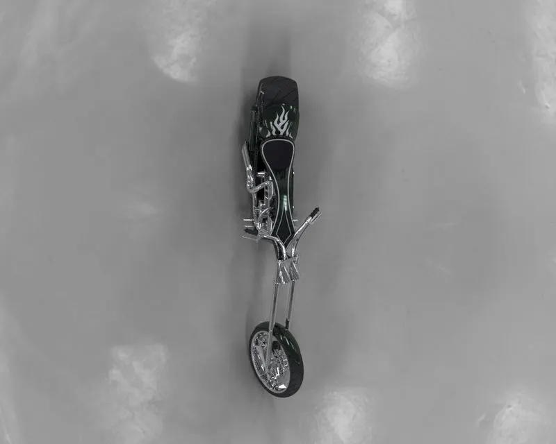
Rendering of American Chopper
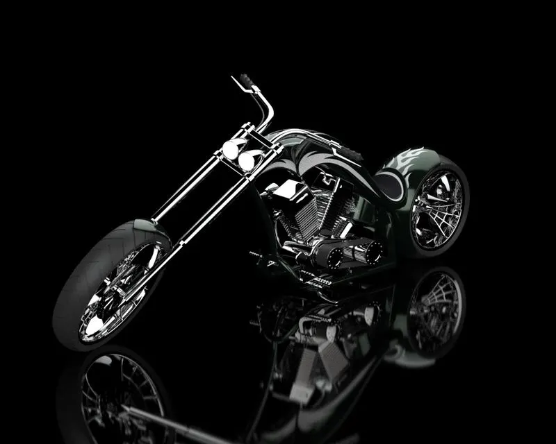
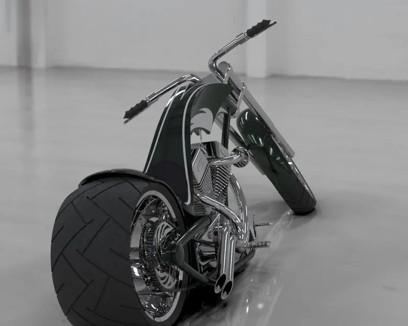
Rendering is the process in which the parts or assemblies are projected and creation of those models to more realistic way to give or assume it as in real environment.
For rendering Solidworks Visualize is used with different Environment Options.
Rendered Images
Front View-Gaurav Sharma
Side View-Gaurav Sharma
Top View-Gaurav Sharma
Isometric View-Gaurav Sharma
Camera SetUp View-Gaurav Sharma
Conclusion
The American Chopper was assembled in the solidworks and rendered in the photoview 360 and Visualize.