Wiring harness routing & packaging Rules Week 3 Challenge
1)
Aim:-
- Download following cad data & define it as Electrical support using Electrical Part design Workbench. Define all the necessary properties.
Given Data:-
- This is given P-Clamp in which we have to define the necessary properties.
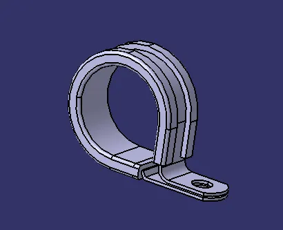
- Define this P-Clamp as Electrical Support.
- Create points and planes by which we can define the entry, exit and base plane for the bundle.
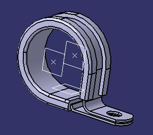
2)
Aim:-
- Download following Back shell cad data & define it as Electrical back shell using Electrical Part design Workbench. Define all the necessary properties.
Given Data:-
- This is the given Back Shell in which we have to define necessary properties.
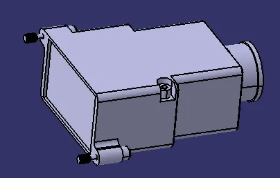
- Define this component as Electrical Backsheel.
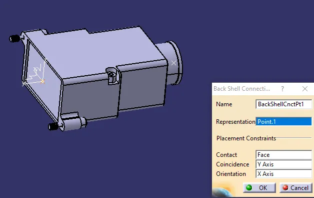
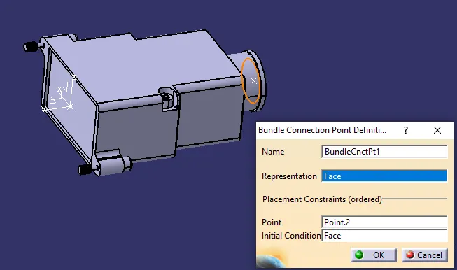
- Create a point and axis for the connector connection point and a point for bundle connection point.
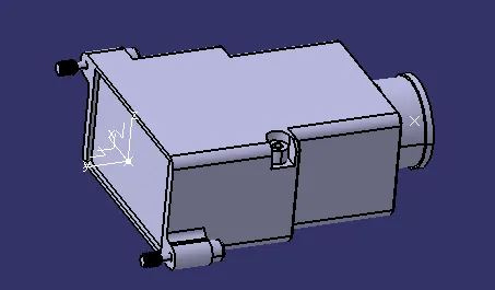
Connector connection Point:
- While defining the connector connection point make sure the X axis pointing towards the locking mechanism and Y axis point toward the direction in which the connector is goint to get in contact with the backsheel and Z axis is depend upon the X and Y axis.
Bundle Connection Point:
3)
Aim:-
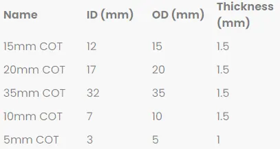
- Create Following Corrugated tubes & Add them in Catalogue under “Slit COT” family.
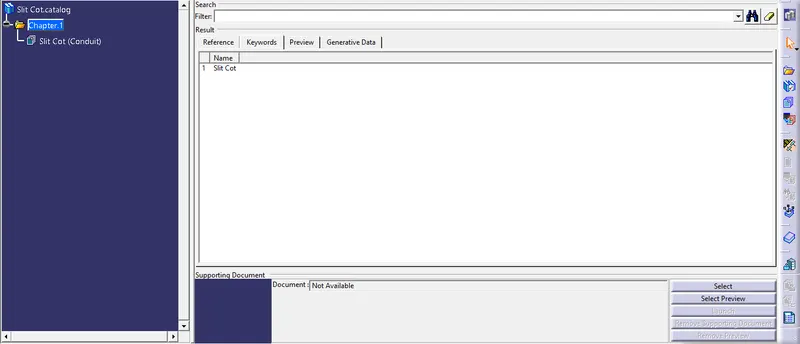
Creating the catalogue:-
- Create catalogue.
- Then add family.
- Save the catalogue in desired location.
Creating Corugated Tubes with Given Data:-
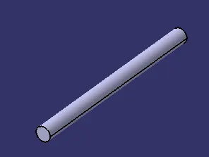
- 15mm Cot:
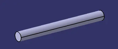
- 20mm Cot:
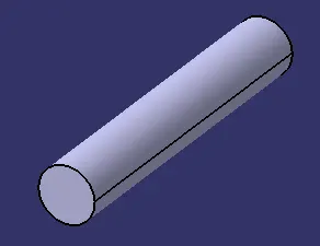
- 35mm Cot:
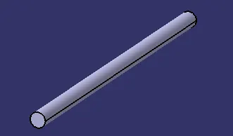
- 10m Cot:
- 5mm Cot:
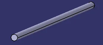
- Then finally add these corrrugated tubes to the catalogue which we have created before with the name of "SLIT COT".