Wiring harness routing & packaging Rules Week 3 Challenge
Q1.
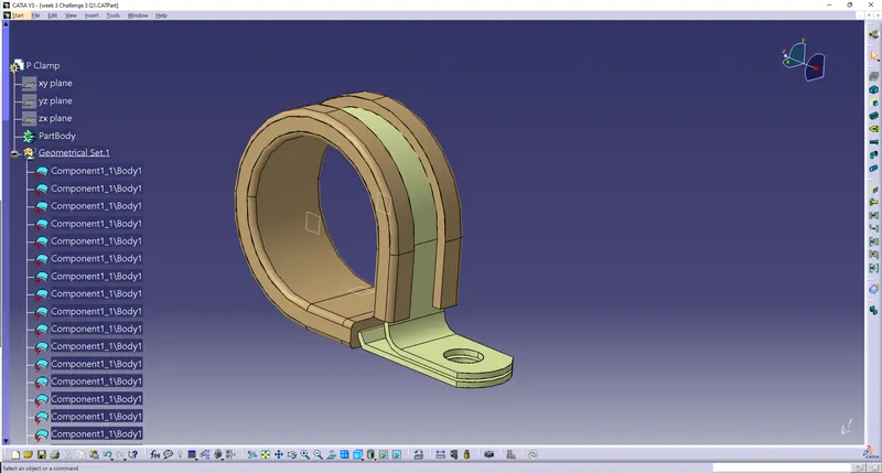
The P-Clamp given in the question is downloaded.
We have to create two points and three planes.
One point should be at the entry and another point should be at the exit.
These Planes should be at the center of the entry circle and the exit circle.
We have to create two planes passing through these points.
Then we have to create a third plane at an offset of 2mm from the base of the P clamp.
After defining the points and planes we have to change the workbench to electrical power design.
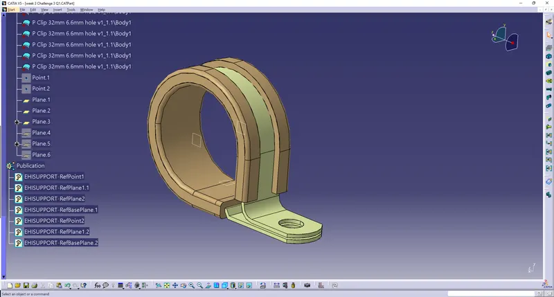
In the electrical part design we have to define the clamp as a support part.
First click on the define support part tool, then click on the body of the clamp.
Then we'll be getting a box in which we have to select the point at one entry and the plane at that entry section,then the plane at exit section and the base plane is to be selected.
Similarly we have to define the other entry point.
Q2
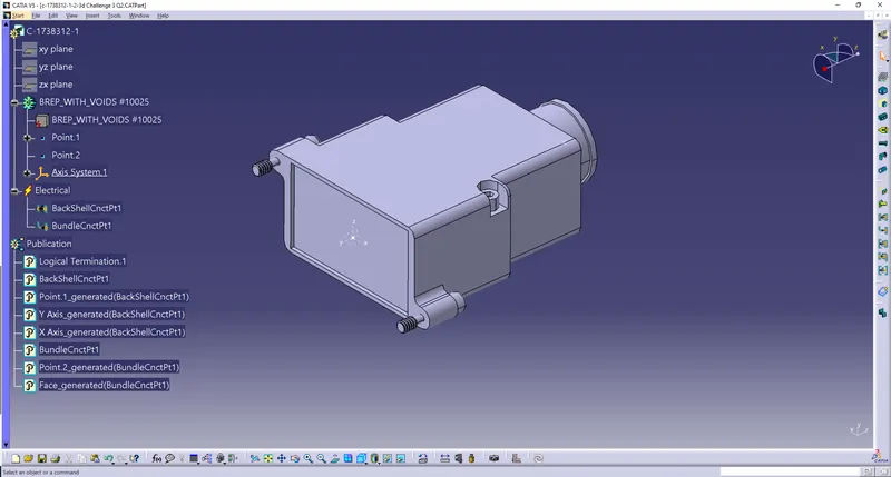
The backshell provided in the question is downloaded.
By default it will be downloaded in the electrical part design we have to change the workbench to mechanical part design.
We have to define two points, one at the center point for the bundle connection point and the second one center point to connect the backshell to the connector.
For the bachelor connection point we have to define a plane with the Y axis normal to the face of contact.
Then we have to switch the workbench to electrical part design.
Then we have to define the backshell using the "define backshell" tool
After clicking the tool you have to click on the backshell body.
Then a box will appear and make the settings to be the default values and click on OK.
Now the backshell is defined as an electrical component.
Now we have to define the backshell connection point.
Click on the " define backshell connection point" tool and select that body of the backshell.
Then select the point the face and the direction Y and direction X.
Then the bundle entry point is to be defined by selecting the point and the face resspectively.
Corrugated tubes are protective coverings given to the wiring harness bundles. Corrugated tubes can be of different kinds.
They may also how different color is so that they can be applied for particular applications.
In CATIA corrugated tubes can be created in the electrical part design workbench.
We have to open a new part and we have to switch the workbench to electrical part design.
The electrical part design we have to click on the "define protection part tool" then click on the part file name in the tree so that we will be getting a window.
In this window we can select the internal diameter and the thickness required for a corrugated tube.
The default corrugated tube will be created with the given values.
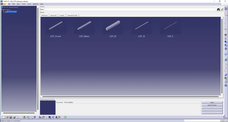
now start now start a new catalogue file.
Click on the add families and add the Slit COT family.
The type of family is conduit.
Then save the file as Slit COT catalogue.
Again open the first quote part we have made and we have to apply a catalog in this part.
In order to do that they have an option called " store device"
click on the store device tool select the catalogue location and select the catalog type.
Now if you are opening the catalogue named Slit COT, We can see all the corrugated tubes that are part of the catalog.