Boeing-747 _ Final_Project
Projecc report on Modelling of Boeing 747-8 Aircraft in Solidworks
Modellimg And Assembly of Boeing 747-8 Aircraft in Solidworks
Introduction
In this project Modelling and assembly of a boeing 747-8 Aircraft is done.The 747-8 is a wide-body airliner from Boeing Commercial airplanes.The First the main body of the aircraft is modelled.It is the biggest part of the Aircraft.Later the Modelling of The Windows,Doors and Hatches etc are done.These are given as surface split features.Then the vertical and the horzontal Stabilizers are modelled.Later the Nose gear and main gear assemblies are done as a separate assembly.The components in the nose gear are nose gear base,Nose gear suspension arm and the wheels.The Main gear has the components,Main gear base,Main gear suspension arm and the Wheels.Later all these three are assembled and the livery of the boeing is applied and proper material and paints are provided for the model the model is later rendered in Solidworks visualizer to make some realistic views.The main components of the Boeing 747-8 that are modelled here are as follows:
- Blueprint setup
- Fuselage
- Belly Fairing
- Nose Cone
- Pitot Tubes
- Cockpit Windows
- Winshield wipers
- Passenger Windows
- Doors and Hatches
- Lights and Antennas
- Auxilliary Power Unit
- Vertical stabilizer
- Horizontal stabilizer
- Static discharge tibes
- Wings
- Flaps and Ailerons
- Flap track Fairings
- Landing Gear axis
- Landing gear Hatches Open
- Landing Gear Hatches Closed
- Wheel
- Nose Gear Base
- Nose gear suspension arm
- Main gear base
- Main gear suspension arm
- Engine
- Livery
- Nose gear assembly
- Main gear assembly
- Boeing 747-8 Main Assembly
The Boeing 747 has a length of 76.3 metre,A height of 19.4 metre and a wingspan of 68.4 metre.It has a maximum take off weight of 4,47,696 kilograms.It is powered by four General Electric GEnx-2B67 turbofan engines each producing a maximum thrust of 296 kilo-Newtons.It is equipped with fly by wire Ailerons and spoilers.747-8 can carry a total of 467 passengers in a three class configuration over a range of 14,430 kilo-meters and cruise at a speed of 0.86 mach(914 kmph)
Objectives
- Understand the various features in surface modelling and part modelling modules in solidworks
- Modelling different components following a proper methodology and assembling these later to create a working assembly.
- To create realistic images of Boeing 747-8 with the solidworks visualizer render engine in solidworks.
Desigh Approach
In Part modelling there is mainly two different approaches that are followed:
1.Surface modelling
In surface modelling the component to create starts as a suface and are not solids.These surfaces can be later converted into solids to further assemble.Using surface modelling comples surfaces can be created that are quite hard to model using solid modelling.
2.Solid modelling
The solid modelling is a modelling criteria in which the body is modelled as a solid itself.The solid modelling features in solidworks are quite elaborate and easy to work with.
The different Design criterias that are used for assembly are as follows.
1:Bottom up Approach
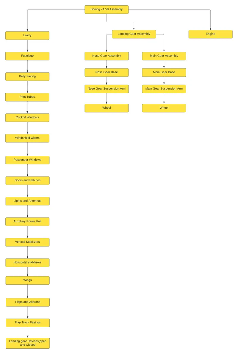
Here each part of an assembly is modelled separately in apart modelling module and are saved as part files in the file path.These parts are later inserted into an Assembly workbench and are assembled together using different relationships between each other.In this project a bottom-up approach is followed.
2:Top-Down Approach
In top-down Approach the part starts as an assembly itself.The individual parts are modeled as individual components within the assembly workbench.One advantage of this method is that we can refer other bodies features in modelling a different component.
Design criteria followed in this project is showed in the chart below:
The main features that are used in this project are as follows.
- Sketch Picture
- Sketch Constraints
- Extrude Boss/Base
- Revolve Boss/Base
- Loft Feature
- Fillet
- Sweep Boss/Base
- EXtrude cut
- Revolve cut
- Swept cut
- Lofted cut
- Circular Pattern
- Linear pattern
- Surface loft
- Offset surface
- Mirror
- Thicken
- Split
- Split line
- Combine
- Mates
- Appearance
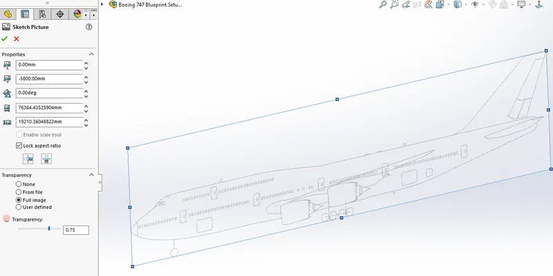
Sketch picture
Sketch picture is a feature inside the sketching environment where we can insert images of the bodies we are going to model as per the dimensions and scaling.this picture can be used as a reference for the modelling.
Sketch Constraints
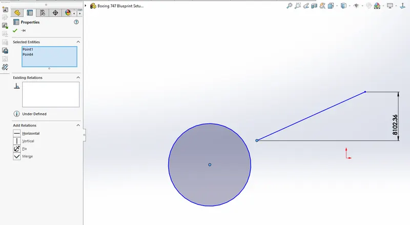
The sketch constraints are used to give relations between different sketch entities.In solidworks we have to make the sketch fully constrained or fully defined.A fully defined sketch will be black in colour.Underdefined sketches will be blue in colour.We have to define a sketch using dimensions and relations.
Extrude Boss/Base
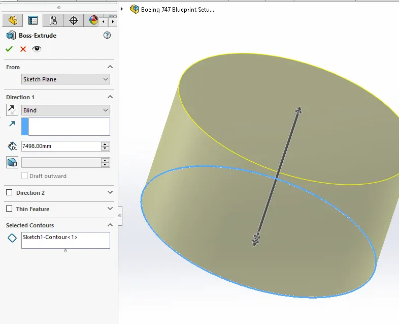
The extrude command in solidworks is used to give thickness to a sketch.If the sketch is closed then the resulting body will be a solid body,if the sketch is not closed it will give a thin feature extrusion where the resulting body has a thickness about the open sketch.
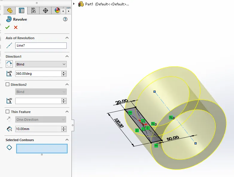
Revolve Boss/Base
The Revolve boss/base is the tool used to make solids of revolution.The closed sketch is revolved about an axis of selection.
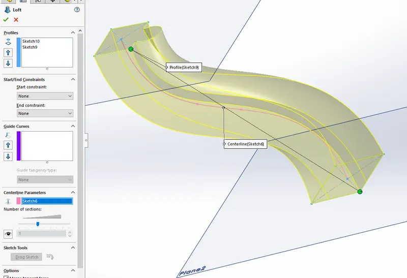
Loft Feature
This feature is used to create a solid with different cross sections at different planes.The path connecting the different cross sections can be controlled.
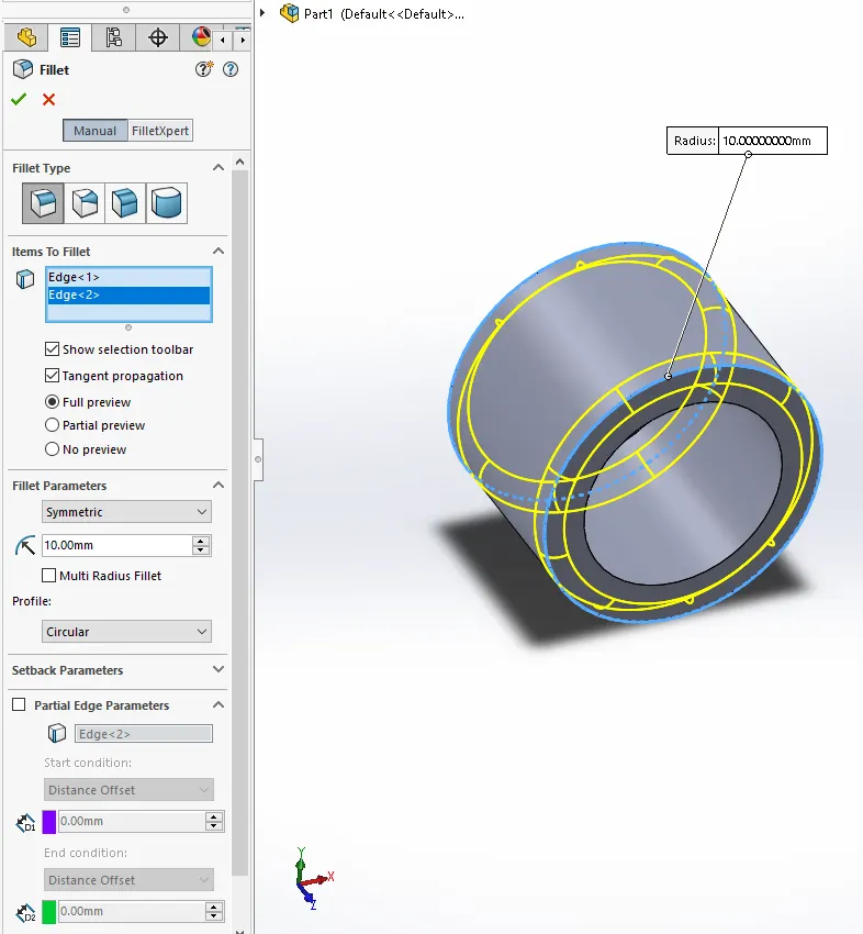
Fillet
Fillet is used to round off sharp edges to give a smooth finish for the edges.This gives a good appearance.This feature will add or remove material as per the edge alignment with the surrounding solids.
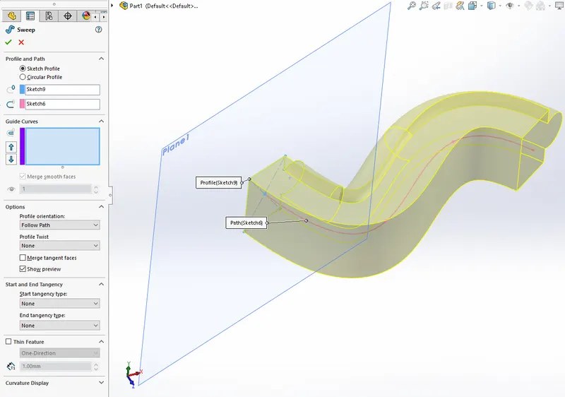
Sweep Boss/Base
The Sweep boss or base is the tool used to create solids such as tubes pipes or wires etc.A profile sketch which is closed is sweep about a path which is open.
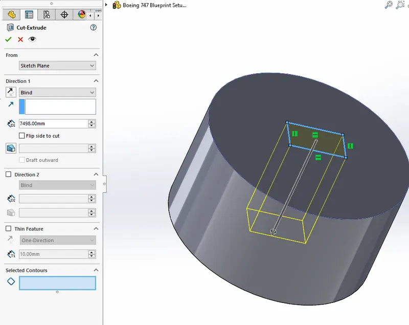
Extrude cut
It is the cut operation similar to the extrude boss/base.It is the material removal version of the Extrude boss/base.All other things are similar.
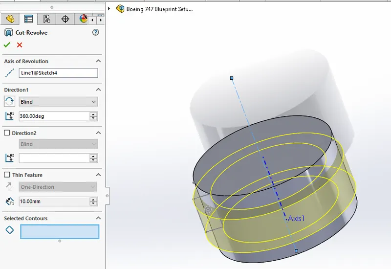
Revolved Cut
The Revolved cut is the material removal process similar to revolve boss/base.The procedure is similar to the boss operation and we need a closed sketch and an axis of revolution
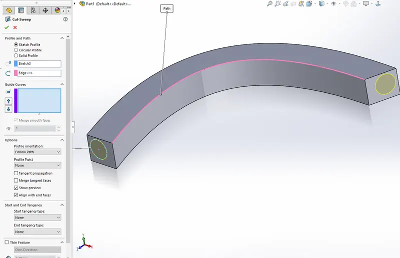
Swept Cut
Swept cut is the material removal version of the Sweep boss/Base.A closed sketch and a path is required.The cutting part should intersect a body,otherwisw it will give error.
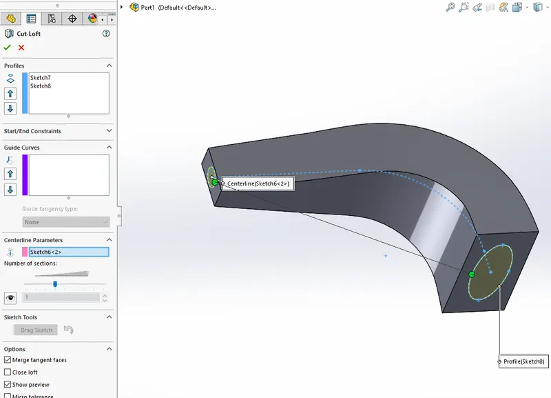
Lofted Cut
lofted cut material removal process off loft boss/base. Here also we require two sketches in two different planes and sketch connects between the two sketches. Complicated cuts can be made using this tool.
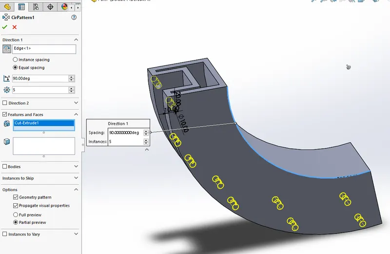
Circular Pattern
Circular pattern feature is used to generate multiple copies of a feature or bodies or faces in a circular path.The number of copies,The angle between copies etc can be controlled.
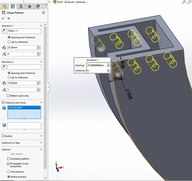
Linear Pattern
Linear pattern is similar to circular patter.This feature produce multiple copies of the Body,Feature,or faces that are selected along a particular direction.
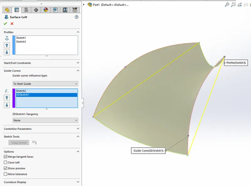
Surface Loft
The surface loft feature can be used to form a surface with different cross-sections.The path connecting the different crosssections can be defined.The guide curves feature is used for controlling the boundary of the surface.
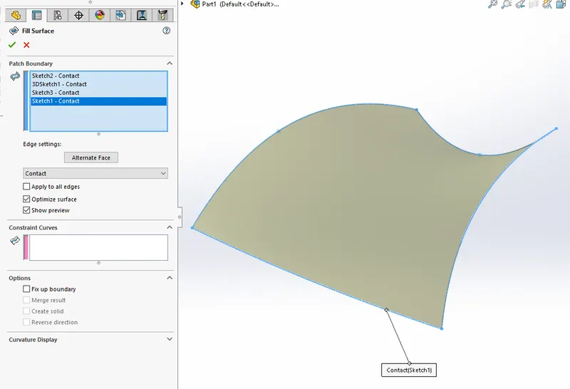
Surface Fill
Surface fill feature is used to form a surface from different sketches which together forms a closed figure.
Offset Surface
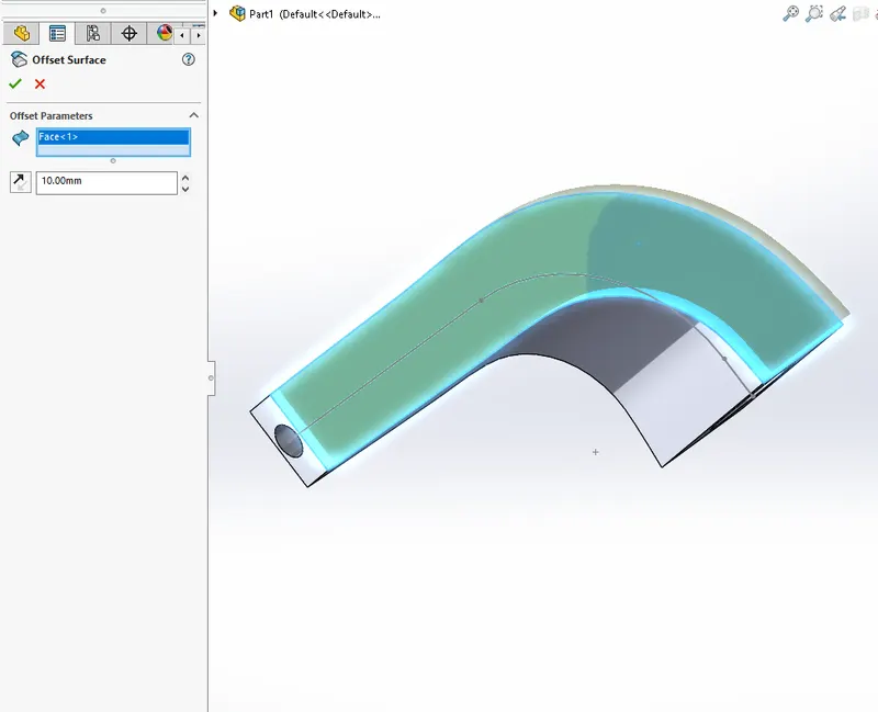
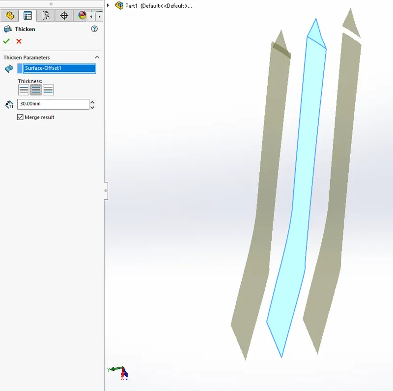
The offset face feature is used to do create a face which is offset from another face. This can also be created as a copy face which is a face at an offset of zero distance. We can later thicken the surface to produce a solid.
Thicken Surface
Split
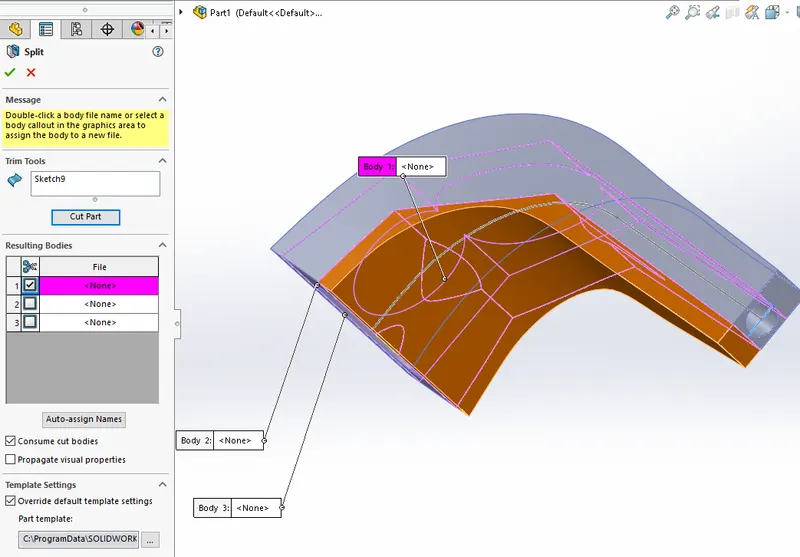
Split tool is a feature used to cut certain parts of bodies using surfaces or sketches etc. We can control which part of the body is to be removed and the removed part can be saved as an external part file. In the figure drawn below the cut is made by a sketch on the body which is ticked-on in blue colour in the detail window will be removed since the consume cut body is activated.
Split Line
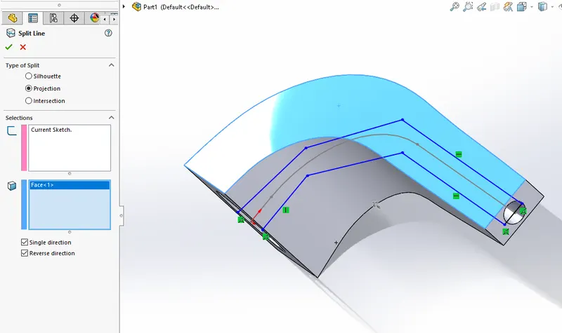
the split line tool is used to split the surfaces off parts. The split and be made by sketches of surfaces. We have to select the type of split as silhouette or projection and what is the sketch used for the splitting and also the face on which splitting is to be effected.
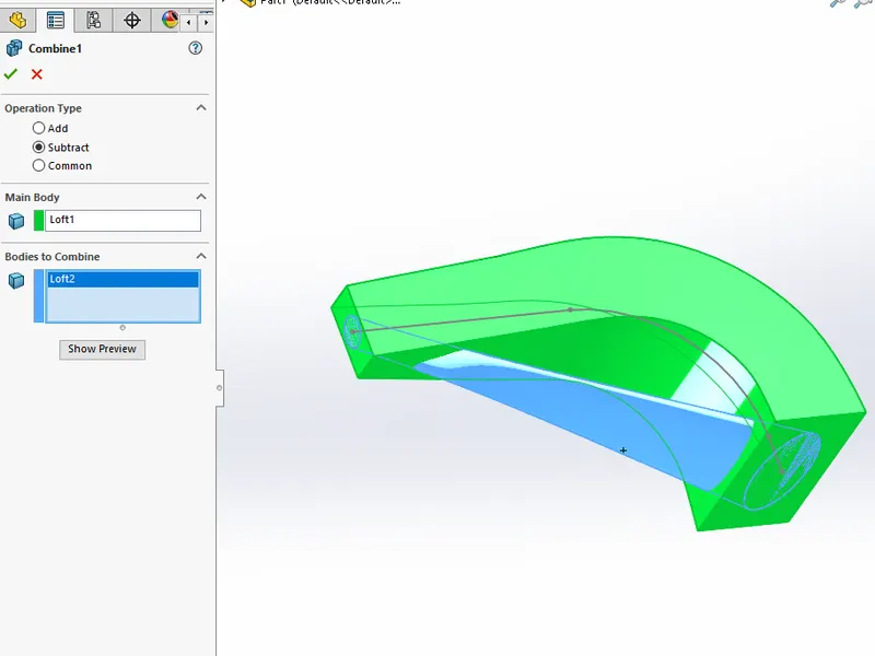
Combine
Combine is a feature used to do add two bodies together which are in contact, subtract one body from another body or take the common part between the two bodies.
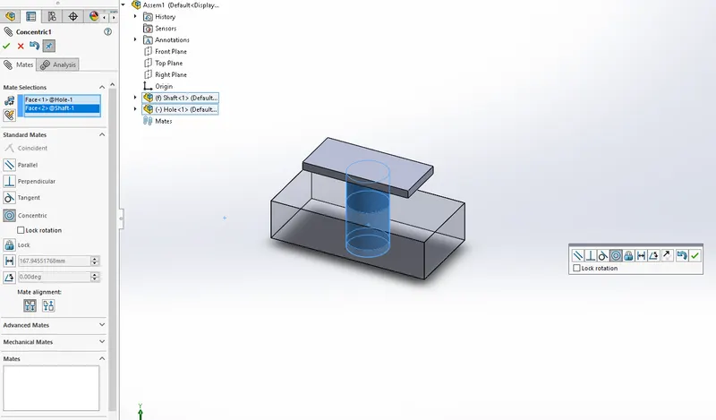
Mates
Mates are used to give relation between the different components.The faces,points,edges etc of one body can be related to another bodies corresponding entities.This forms an assembly.We can control select two entities and let off the control button to give mates instantly.
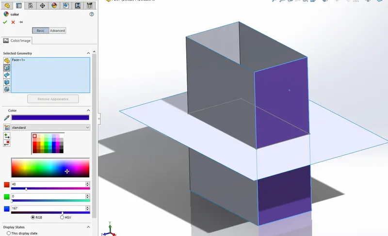
Appearence
Appearence feature is used for giving colours and patterns for solids,surfaces or features.We can give the RGB code for the colours to be given.
The main components that are modelled based on the procedure that we followed through the project is shown below:
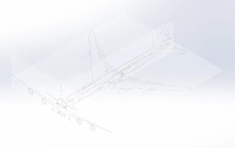
Blueprint Setup
The first step towards starting the Boeing project is setting up the blueprint because we need a reference of the airplane.This is done by using sketch picture tool in sketch environment. The length and width dimensions are given scaled to size and the transparency is reduced.
Fuselage
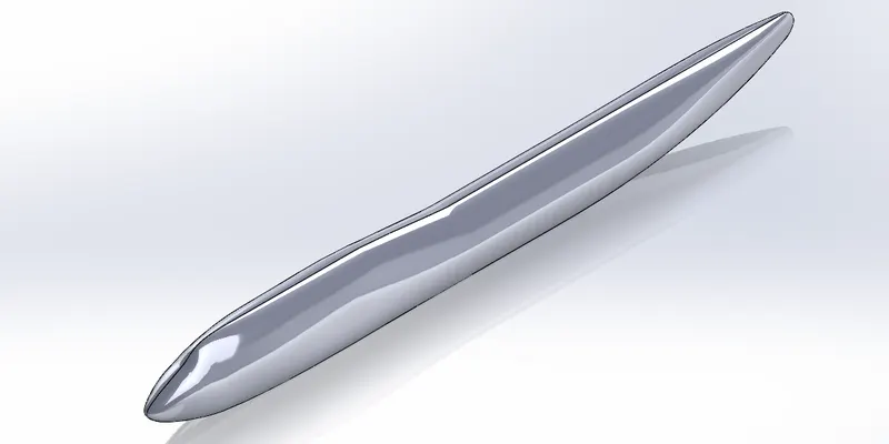
Fuselage is the main base part of the Boeing 747 airplane. All other components have to be attached to this part. This is where the the passenger compartment and cockpits are situated. We are connecting the wings the ailerons and the vertical stabilizers etc to the fuselage. This part is created by using the loft Boss/base feature in SolidWorks. Multiple sketches a drawn as profiles in different planes which are offset from the front plane. Half of the Fuselage modelled and is then mirrored and combined together.
Belly Fairing
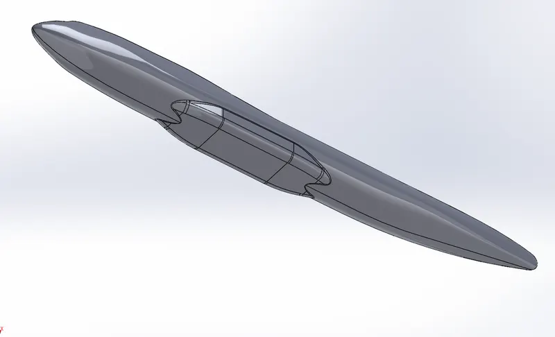
Belly fairing is the part of the airplane to which the landing gears and the wings are attached. This should be more stardier than the other parts of the airplane because it takes all the load during take off and landing. This is modeled as an extruded Boss/Base and fillets are applied.These are also called wing to body fairings.This can ba used as extra cargo space.
Nose Cone
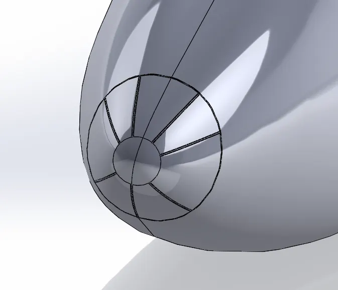
Nose cone is the front part of the airplane. This is made of a non conducting material. Certain static tubes are provided to dissipate the lightning strikes. This is made as a split line tool. Later sweep tunes used to produce solid tube like structures.This is designes with atmost care to do not cause any drag and to be in a more streamline fasion since this is the part first encounters the oncoming air.These are made from radar transparent materials, that is fitted over a radar transmitter/receiver.They provide protection to the transmitter electronics from the weather and other elements (rain, hail, cloud, sand) and often require to be specially shaped for the application
Pitot Tubes
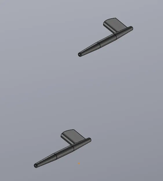
Pitot tube is the front facing small tubes that are projected on the two sides of the airplane into the Airstream. This collects the data about the velocity of the airplane the attitude of the airplane etc. This works by finding the difference between the static and stagnation pressure readings. The features which are used are extrude,chamfer,revolve, fillet etc
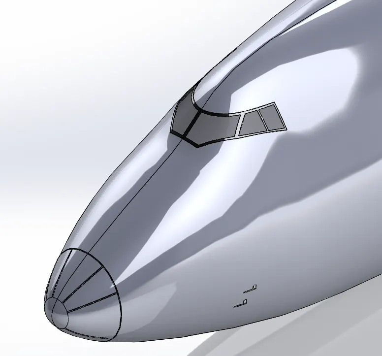
Cockpit Windows
Cockpit windows are the front windshields of the aircraft. These are reinforced glasses provided at the front of the aircraft thereby enabling the pilots to see the front. Just behind these windows are the cockpit where control mechanism and electronics are provided. Cockpit windows are modelled by using split line tool, offset face, thicken face and fillet.
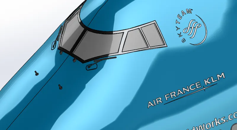
Windshield Wipers
windshield wipers are used wiped windshield glasses. This pair of wipers wipes of the dirt and water stick on the front windshield. The main tools used are projected curve, sweep boss/base, move or copy body, fillet etc.
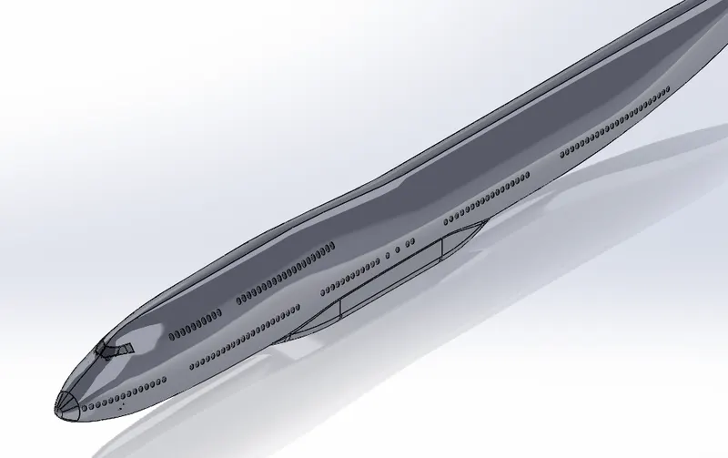
Passenger Windows
passenger windows are modelled using the split line tool. The window frames are later made as a surface offset, these offset surfaces are then thickened and fileted.
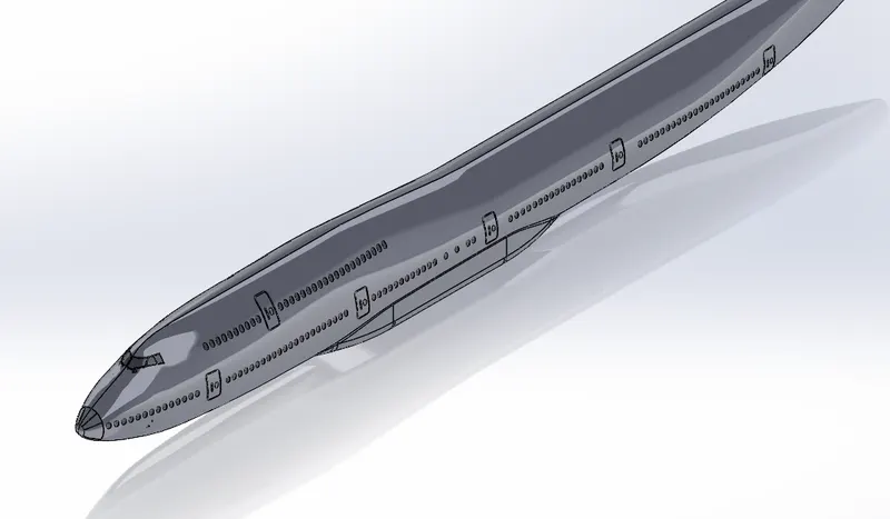
Doors and Hatches
Passengers and pilots can enter and exit the airplane through the doors of the airplane. Hatches are provided to get in and exit out of the storage spaces in the aircraft. A cockpit escape hatche is provided at the top of the cockpit which can be used by the pilots to escape out of the aircraft in case of an emergency.
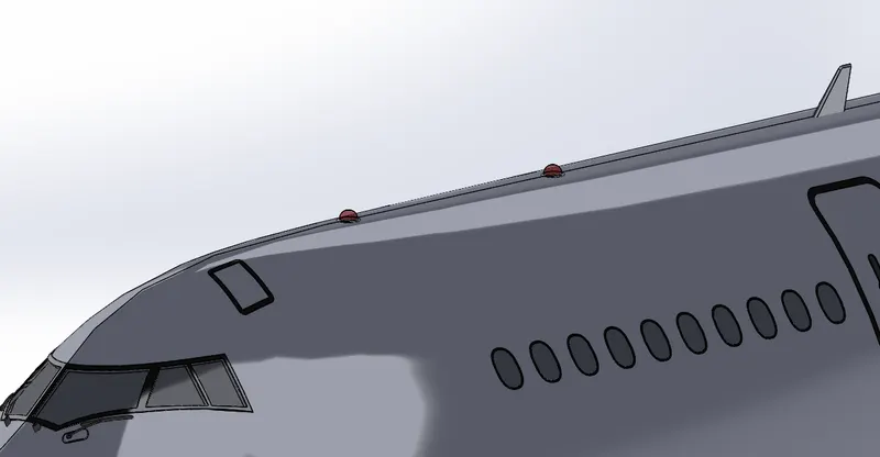
Lights and Antennas
lights and antennas are provided on top of the aircraft and on the wing tips.lights include Position, anticollision, landing, and taxi lights are common examples of aircraft exterior lights. Some lights are required for night operations. Other types of exterior lights, such as wing inspection lights, are of great benefit for specialized flying operations.An anticollision light system may consist of one or more lights. They are rotating beam lights that are usually installed on top of the fuselage or tail in such a location that the light does not affect the vision of the crewmember or detract from the visibility of the position lights. Large transport type aircraft use an anticollision light on top and one on the bottom of the aircraft. Figure 9-177 shows a typical anticollision light installation in a vertical stabilizer.These lights serve different purposes like communication. The antennas are mainly used for communication with the ground centres.These antenna sare also called aerials.The main types of antennas are Communication antennas, GPS Antennas,Loran antennas or long range antennas,Loop Antennas, market beacon antennas,Navigation antennas,Radio altimeters,UHF antennas etc.
Auxilliary Power Unit
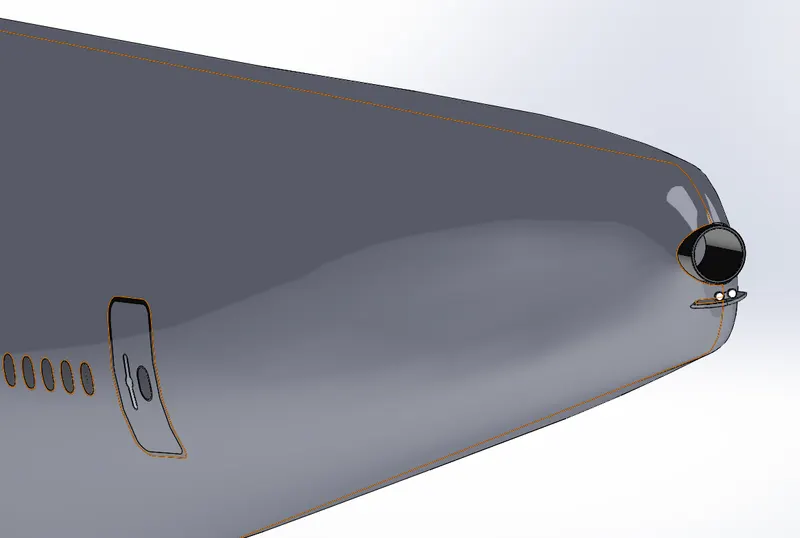
An auxiliary power unit (APU) is a device on an aircraft that provides energy for functions other than propulsion like HVAC systems and other electrical needs.They locate at the tail of aircrafts mostly.. Aircraft APUs generally produce 115 volts Ac current at 400 Hz to run the electrical systems of the aircraft. They supply bleed air for bootstrap cooling system of aircraft and also for starting of the main engine.
Vertical Stabilizer
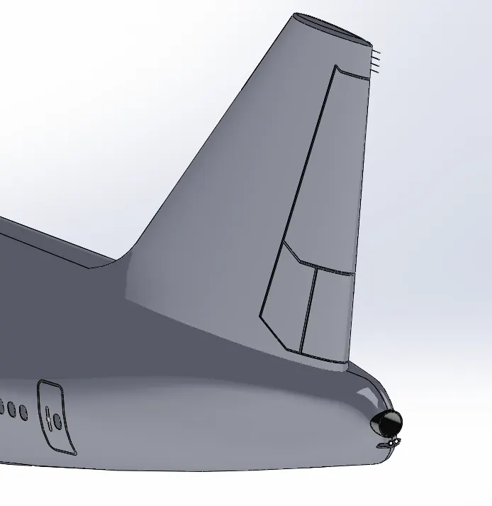
A vertical stabilizer provides directional stability for the aircraft which can also be termed as yaw.They comprises a fixed fin and movable control rudder hinged to its rear edge.When an aircraft encounters a horizontal gust of wind, yaw stability causes the aircraft to turn into the wind, rather than turn in the same direction.
Horizontal Stabilizer
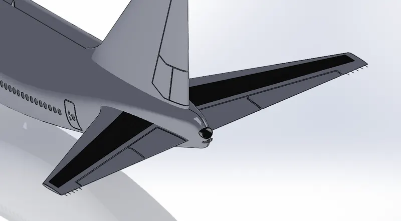
Horizontal stabilizer is at the tail of the aircract.The function of the horizontal stabilizer is to provide stability from pitching motions.Thses are motions resulting in the nose up and down motion of an aircraft.Elevators are provided on the horizontal stabilizer to provide the control of pitch during manuering.
Static Discharge Tubes
Static dischargers, also called static wicks or static discharge wicks, are devices used to remove static electricity from aircraft in flight. They take the form of small sticks pointing backwards from the wings, and are fitted on almost all civilian aircraft.
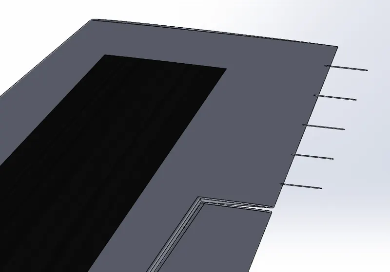
Wings
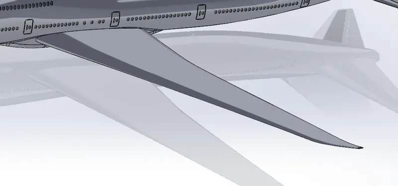
These are the aerodynamic surfaces that mainly proides the lift for the aircraft.These works on the principle of Bernoulli's theorem.When air flows past wings,it gets accelerated above the wing more than at the under wing portion.This creates a pressure gradient which pushes the aircraft up.
Flaps And Ailerons
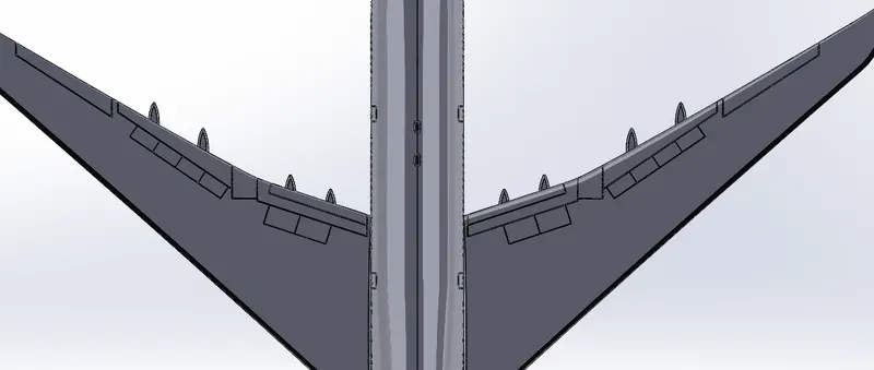
Flaps and Ailerons are control surfaces on the main wing of an aircraft.These control surfaces can be controlled from the cockpit by the pilots to create a lift and drag condition suitable as per the situation.Ailerons can be altered to produce more lift during takeoff and under normal flight they stay straight.Flaps can be protruded to give aerodynamic braking during landing.
Flap Track Fairings
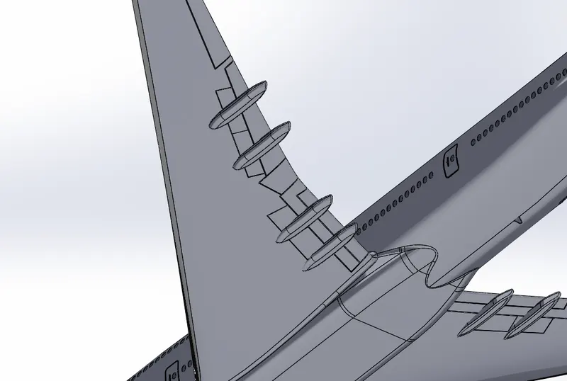
A flap track fairing is a secondary structure whose function is to provide an aerodynamic cover and so reduce drag.They house the workings of the inboard and outboard flaps. Within these structures, the jackscrew, carriages, gearboxes, and associated mounting bracketry are very un-aerodynamic. Therefore, the canoe-like fairings cover them.
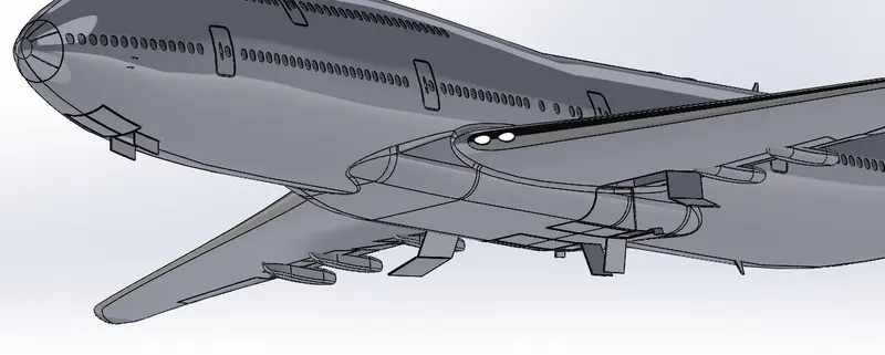
Landing Gear Hatches open
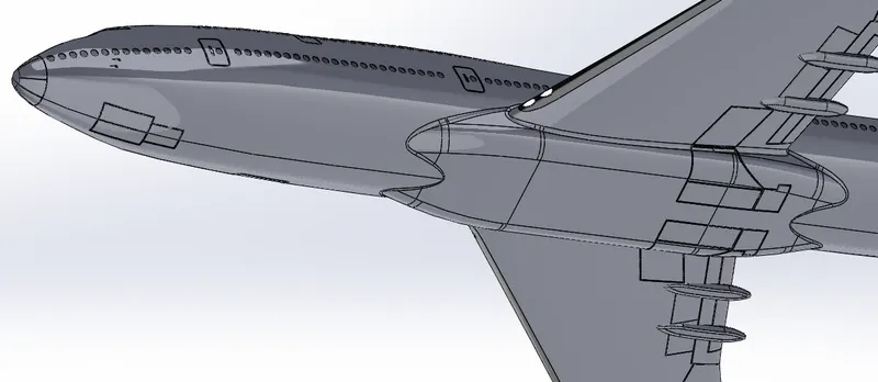
Landing gear hatches are the doors which open to give the nose and main landing gear to protrude out of the aircraft during landing and ground manuering.During flight these gears are extremely draggy and these are to be pulled back into the aircraft body to produce a more streamlined surface and thereby to reduce the drag.
Landing Gear Hatches Closed
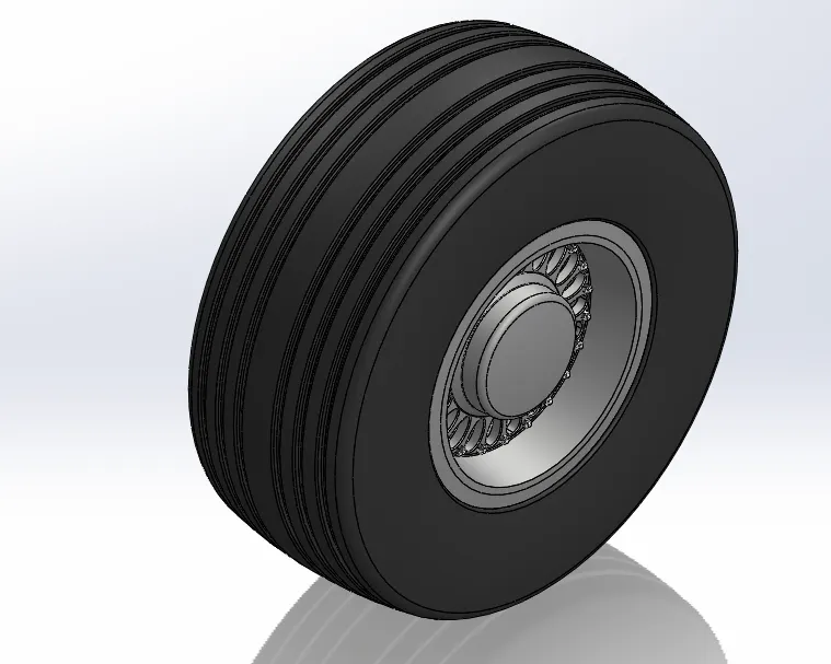
Wheel
They support the entire weight of the aircraft during taxi, takeoff, and landing. The typical aircraft wheel is lightweight, strong, and made from aluminum alloy. Some magnesium alloy wheels also exist. Early aircraft wheels were of single piece construction, much the same as the modern automobile wheel. As aircraft tires were improved for the purpose they serve, they were made stiffer to better absorb the forces of landing without blowing out or separating from the rim. Stretching such a tire over a single piece wheel rim was not possible. A two-piece wheel was developed. Early two-piece aircraft wheels were essentially one-piece wheels with a removable rim to allow mounting access for the tire.
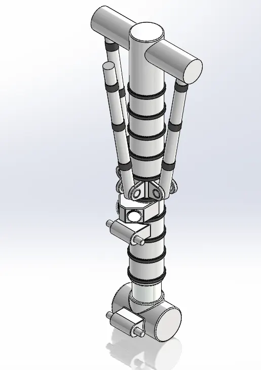
Nose Gear Base
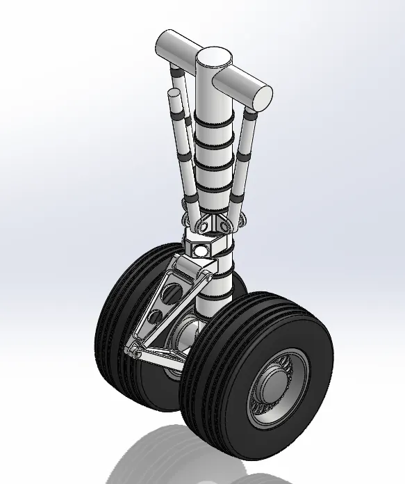
This is the Base part of the nose gear of the Boeing 747-8.This is connected to the nose of the aircraft and supprots the whole front portion of the aircraft.The Tubular portion consists of a shock absorber with hydraulic oil filled in it.There is also mechanism to push the nose gear in and out of the belly.This mechanism is mostly hydraulic.
Nose Gear Suspension Arm
This arm gives directional constraint for nose gear shock absorber travel.This acts as a steering connection from top tube to the bottom tube of the shock absorber.
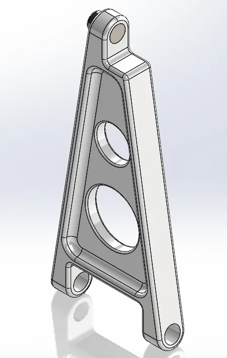
Main Gear Base
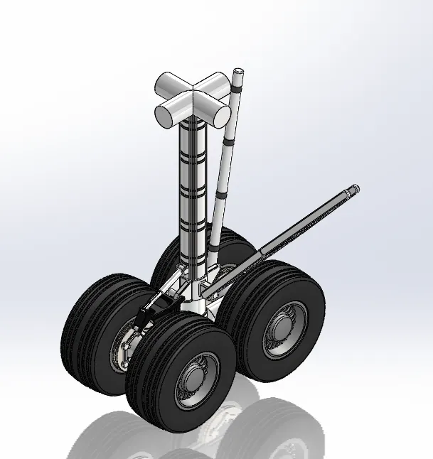
Main gear base is the base of the main landing gear which is situated at the rear of the aircraft.Boeing 747-8 has four of these main landing gears.These also has shock absorber filled with hydraulic oil.
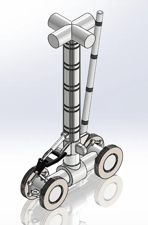
Main Gear Suspension Arm
The main gear suspension arm connects between the top of the shock absorber tube to the bottom of the shock absorber tube.This maintains the track of the aircraft irrespective of the suspension travel.
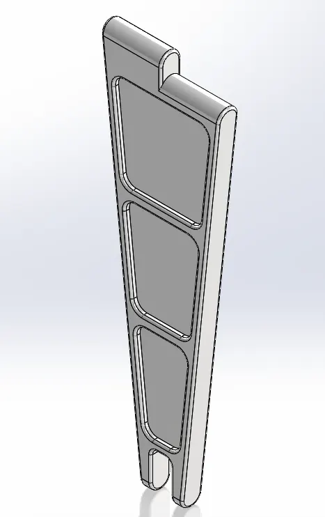
Engine
The engine is the main power house of the Boeing 747-8.The 747-8 has 4 of these turbofan engines.The engine model is GEnx-2B67 from General Electric.Each engine is capable of producing a maximum thrust of 296 kilo-newtons.The rear part of the engine has zig zag shape.This is provided to reduce the noise from the engine.This is a high bypass ratio turbofan engine.
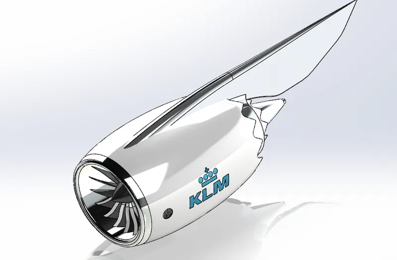
Livery
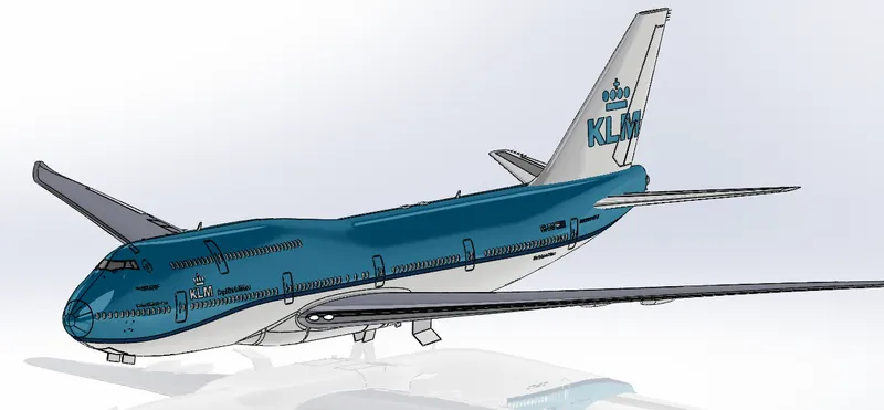
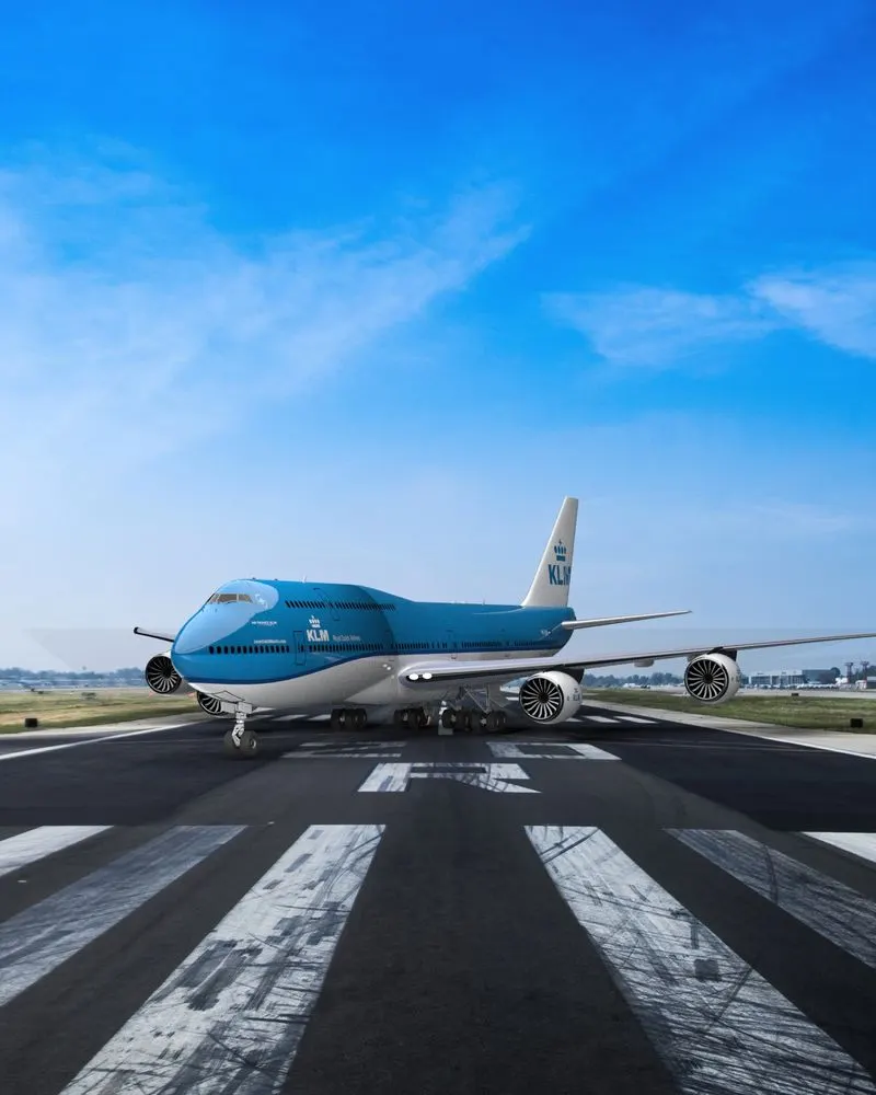
The livery applied here is of KLM airline from france.These are given as split line and later material is applied to proper sections.
Nose Gear Assembly
Nose gear assembly holds the nose gear base, Suspension arm, and two wheels.
Main Gear Assembly
Main gear assembly consists of main gear base,suspension arm,and a set of four wheels in each landing gear.These house the brake rotors where multiple stator and rotors are inbetween arranged and is compressed by a set of hydraulic cylinders to apply brakes.All of these are modelled as single component here.
Boeing 747-8 Main Assembly
All of the above components are assembled to form the full assembly of boeing 747-8 aircraft.The components are arranged together using proper mated such as distance mates between planes,coincident mates, concentric mates,Mechanical mates such as gear mates between the front and rear landing gear.
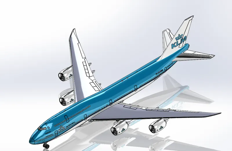
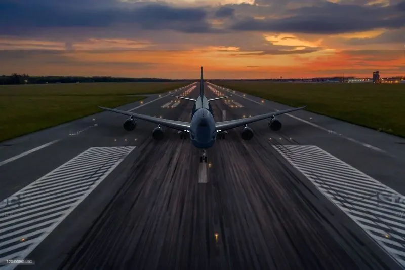
Rendering
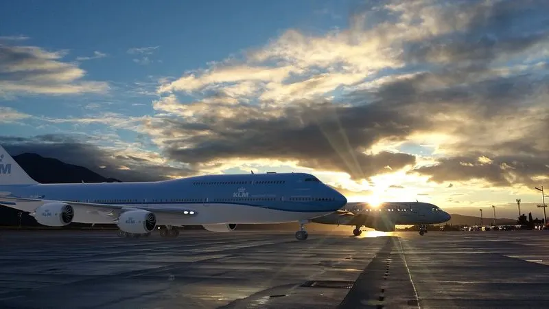
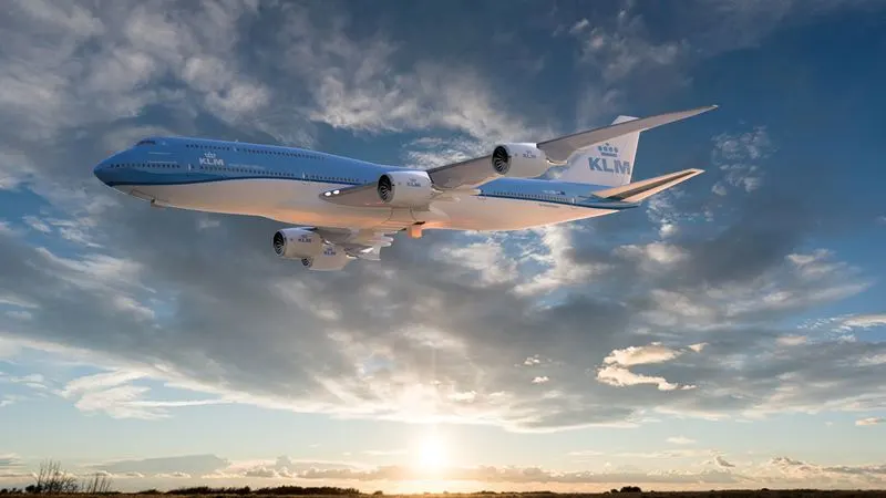
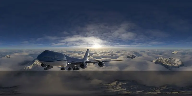
The full assembly is Rendered using the Solidworks visualizer giving proper lighting and background.Solidworks visualize is a standalone Render engine for Solidworks.This works independent of Solidworks so there wont be any licence issues when doing the rendering.In visualize also we can change the Environment.Plates can be added as background images.Camera views can be changed.Views can be changed from perspective to orthographic.The rendered images are provided below.
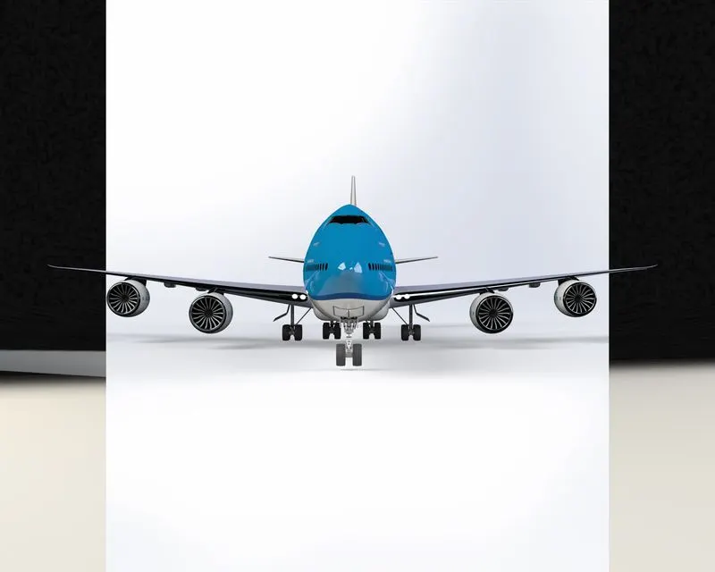
Boeing 747 Front view
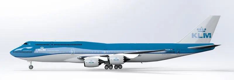
Boeing 747-8 Side View
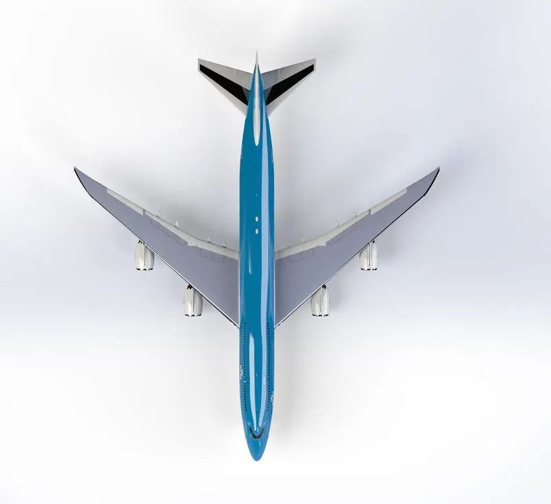
Boeing 747-8 Top View
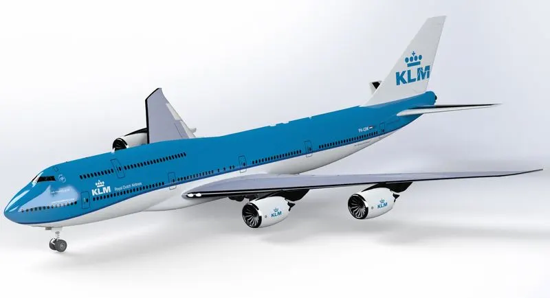
Boeing 747-8 isometric View
Conclusion
The project gives the opportunity to learn about Solidworks and the features in solidworks part modelling such as solid modelling and surface modelling.Also the assembly of the Boeing 747-8 gives a deep understanding about the different assembly mates.The Solidworks visualizer is very good in giving realistic images of parts modelled and gives the opportunity to play with out creativity.