Photo Realistic Rendering
Modelling Of American Chopper In Solidworks
Introduction
This project deals with the design of an American chopper in Solidworks.All the components are modeled using the tools available in solidworks.First start with the attachment of a image of the chopper in its side view as a sketch picture that is a feature in Solidworks.We can make the picture to appropriate sizes.All the main Commands in the Solidworks User Interface is learned in detail and used appropriate tools at appropriate times to model each components separately.Later these components are then assembled using the assembly Workbench in Solidworks.Later the assembly is then rendered in photoview 360 and Solidworks visualizer.The coponents that the American Chopper Assembly has are.
⦁ Chassis
⦁ Engine
⦁ Gas Tank
⦁ Oil Tank
⦁ Front Fork
⦁ Front Fender
⦁ Rear Fender
⦁ Front Wheel
⦁ Rear Wheel
⦁ Kickstand
⦁ Footpedal
⦁ Transmission belt
Objectives
⦁ To be familiar with the User Interface of Solidworks 2019.
⦁ To Understand and Use the Basic commands in Solidworks Modelling environment.
⦁ To be familiar with modelling complicated parts and their design criteria
⦁ Learn about the Assembly module in Solidworks and to assemble the different components.
⦁ Learn about the different rendering features like Decals,Appearance, Environment, Camera etc.
⦁ To be familiar with the tools and User interface of Photoview 360 which is a Which is a rendering adding in solidworks.
⦁ To be familiar with SolidWorks visualizer which is a standalone rendering platform for SolidWorks
Design Approach
There are mainly 2 different types of approaches are used in assembly .One of it is top down assembly and the other is bottom up assembly.
⦁ Bottom up assembly
In bottom up assembly we model each and every part as a single parts and then save them as part files and assemble later in the Assembly module in SolidWorks.In this case if any changes required in the assembly then we have to open the part separately and then change it
⦁ Top Down Assembly
In top down assembly we start with an assembly itself and then design the parts in the assembly workbenchand then give constraints between different parts.This allows the use of other other parts features to model another part.So the geometries from other parts can be used as a reference.
Both these kinds of assemblies are possible in SolidWorks. Here in this project a bottom up assembly is used . So all the parts above mentioned that are designed separately and saved as part models and then assembled later .
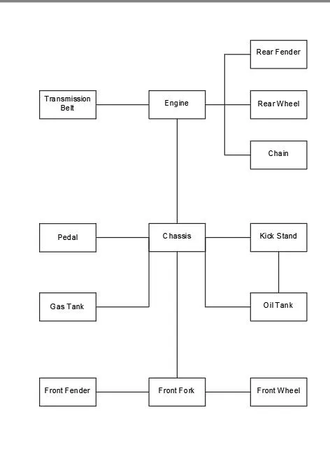
The main features that are available in SolidWorks that used in this project are As follows:
⦁ Extrude Bose/base
⦁ Revolve boss/base
⦁ Fillet
⦁ Extrude cut
⦁ Revolved cut
⦁ Shell
⦁ Linear pattern
⦁ Circular pattern
⦁ Curve driven pattern
⦁ Projected curve
⦁ Chamfer
⦁ Mirror
⦁ Sweep
⦁ Loft
⦁ Mate
Extrude Boss/Base
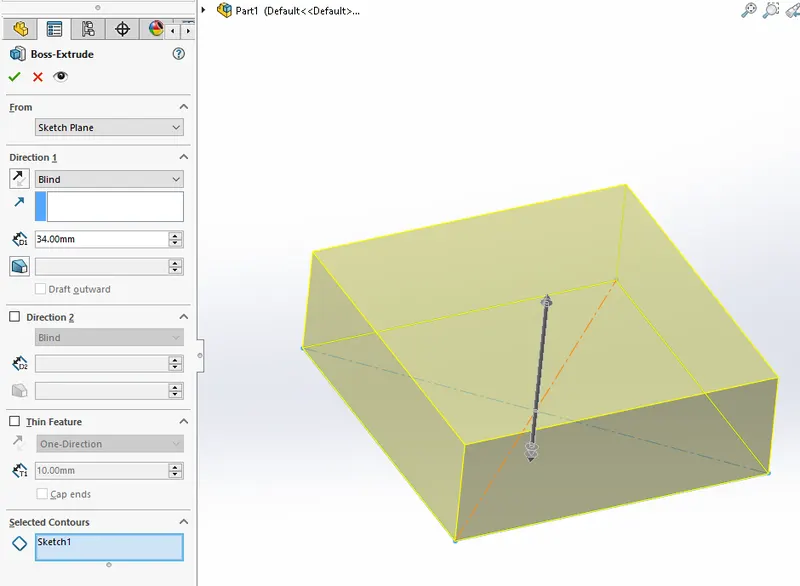
The Extrude Boss/Base feature is used to add thickness to a 2-D sketch.The sketch needs to be fully defined and full of closed loops.After we created a sketch full define exit sketch we can use extrude feature to give thickness to the sketch .The thickness can be controlled as dimension or can be given as other methods like up to next,Midplane,Through all etc.We can add thickness in different directions and upto a surface or a vertex.
Revolved Boss/Base
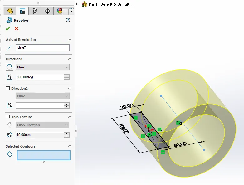
The revolved boss/base feature is used to produce solids of revolution .This feature adds material play revolving fashion .This feature also needs a closed sketch which is fully constrained and axis axis to revolt the sketch around .The Axis can be generated in different ways ,It can be The lines of the sketch or axis of other revolved bodies .We can control the angle off revolution in different direction .If the newly created body intersects with another body then we have two options, either merge with the previous body or make a separate body.
Fillet
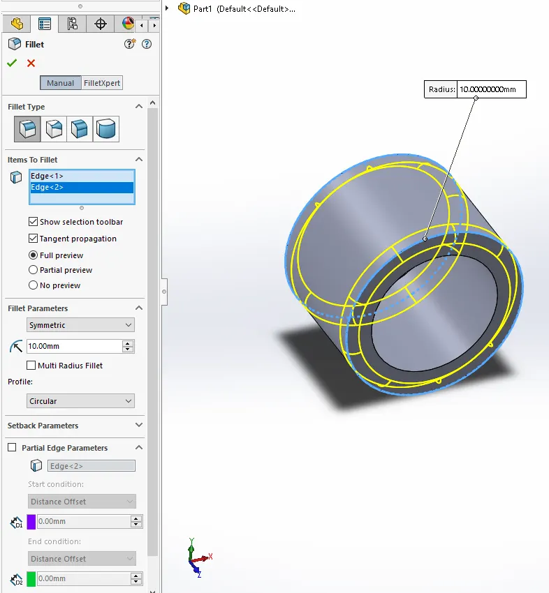
The fillet feature is used to give curves to corners.We can give fillets of any radius And we have to select the appropriate edges Where the fillets are to be given .We can also give face-face fillet, variable Radius fillet and full round fillet.The intelligence selection that is with the fillet is of very good usage In large number of edges easily.Giving fillets to certain solid bodies ensure there won’t be any stress concentration.
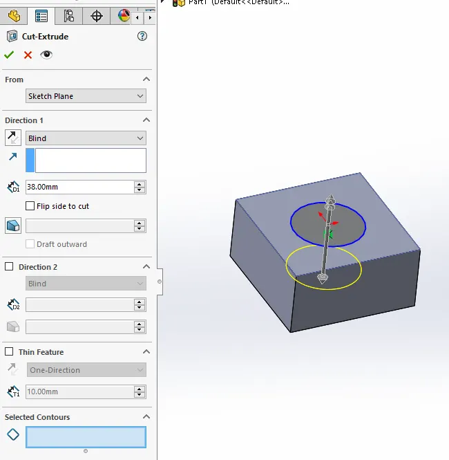
Extruded Cut
This is the material removal process which is Comparable with extrude boss/base.This process removes material constrained sketch from a Body.Here also we can control depth of cut using different methods like dimension or up to face Upto a vertex tax midplane etc .
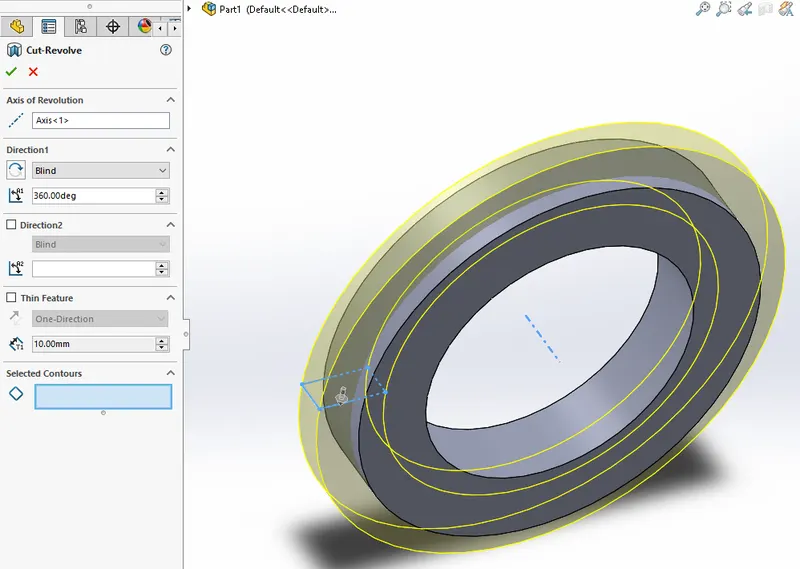
Revolved Cut
Revolved cut is similar to revolve browser base ,It removes material from a part.It also requires a sketch and an axis of revolution .The angles of revolution can be controlled in different direction.
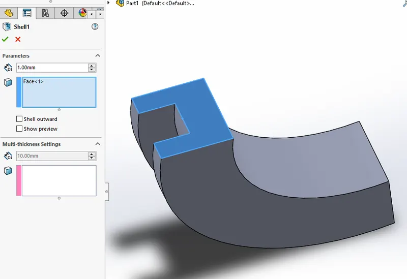
Shell
Shell is also a material removal process which can be used to produce container like components .From a solid body we can take material to make it a hollow body with a particular wall thickness .We can remove any of the faces or not.The fillets produced outside the body will be replicated inside also .We just have to give the thickness and the surfaces to remove.
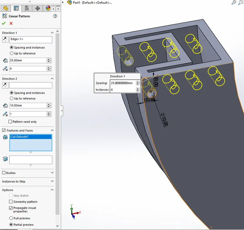
Linear Pattern
The linear pattern tool is used to produce multiple copies open part or feature at once along X&Y directions or a given direction. We can control the number of copies ,The distance between each copy And the direction also
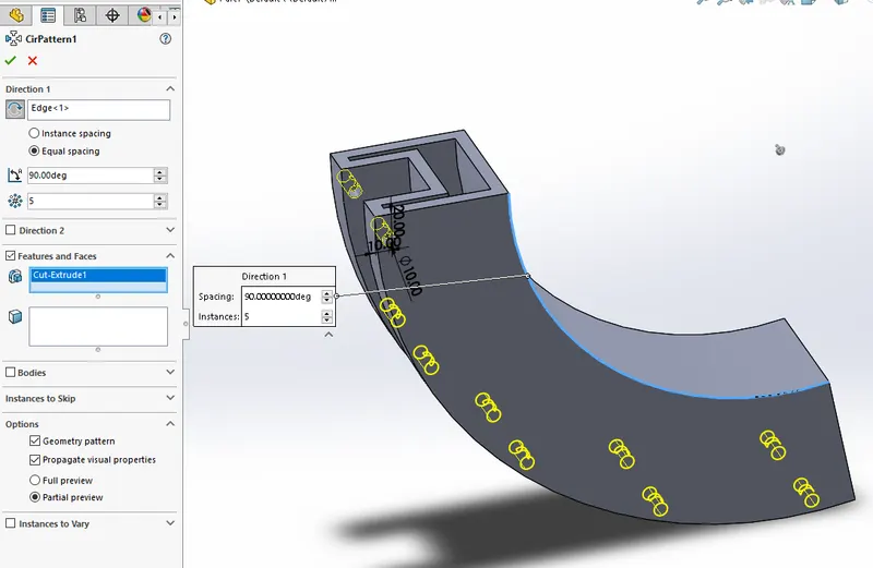
Circular Pattern
Circular pattern is used to produce multiple copies along a circular path.The number of copies, The angle between copies ,Etc can be controlled .Both bodies and features can be used for circular pattern .
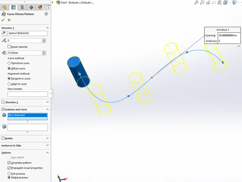
Curve Driven Pattern
The curve driven pattern is used to produce multiple copies of parts alone a particular direction like arc or spline.Both bodies and features can be used for pattern.We can control the number of copies and the distance between each copy And the direction of production of copies along the path.
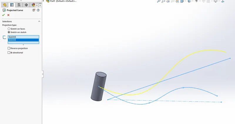
Projected Curve
The projected curve feature can be used to produce complicated curves from projection curves drawn on two perpendicular planes .Here we can produce 3D curves using 2-D curves in 2 different planes .This feature is used to produce the path for exhaust .
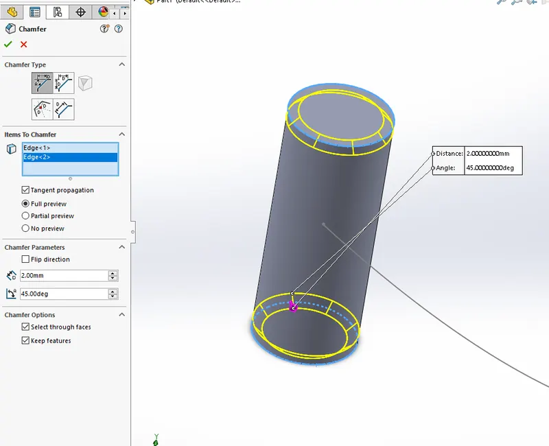
Chamfer
Chamfer is used to produce bevel faceson the corners of solids like shown in the figure.The angle and distance of the bevel can be controlled Feature.
Mirror
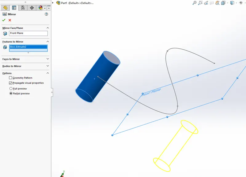
The mirror feature is used to produce components of symmetry. So to model a component that has a symmetry we only have to model half of it and then use the mirror tool to make draw using a playing at the intersection between the two halves.We can use both bodies and features for mirroring.
Sweep
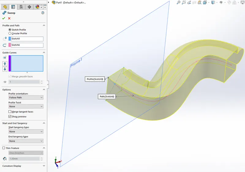
Sweep is used to produce bodies that have a cross section Which flows along a path.So sweep feature requires two sketches, one contains a profile and other contains a path through which the profile is to flow.The profile should be a closed sketch and the pathis to be open.
Loft
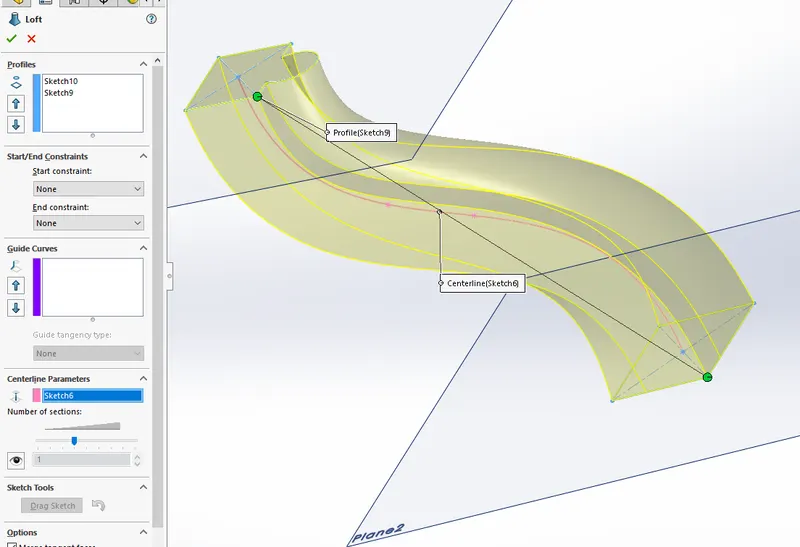
Loft is used to produce bodies that have multiple cross sections along a path .So here we need different sketches which are at different cross sections and lines connecting those cross sections which act as boundaryies or centerline.This feature is used to produce the kickstand .
Mate
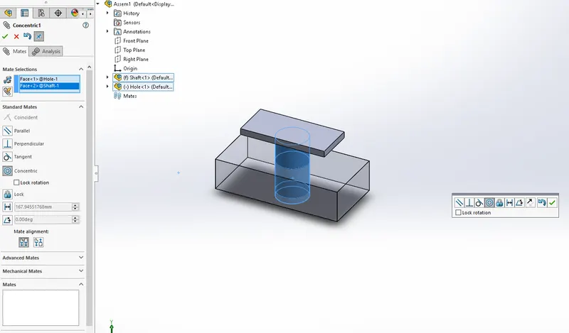
Mates are like relations applied to different bodies in an assembly module.This restricts the movement of parts relative to the other parts and positions them with respect to each other . The different meats and we have used in this model are coincident, parallel, angle, tangent, distance etc .
The features that we have discussed above are used to produce the major components in the American chopper assembly .
Chassis
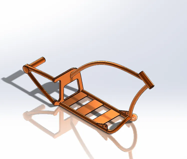
The chassis is the main component of the Chooper to which other components are attached to .The chassis services to mainframe for the American chopper.The modelling of the chassis starts with them side view of Chopper as sketch picture in SolidWorks.Later loft features are used to produce the tubes .They are connected by using components produced using extruded boss .Fillets are applied to certain sharp edges.The appearance given to the chassis is siena which is a car paint.
⦁ Sketch Picture
⦁ Splines
⦁ Sweep
⦁ Reference planes
⦁ Extruded boss/base
⦁ Revolved boss/base
⦁ Fillet
⦁ Appearance
⦁ Combine
Engine
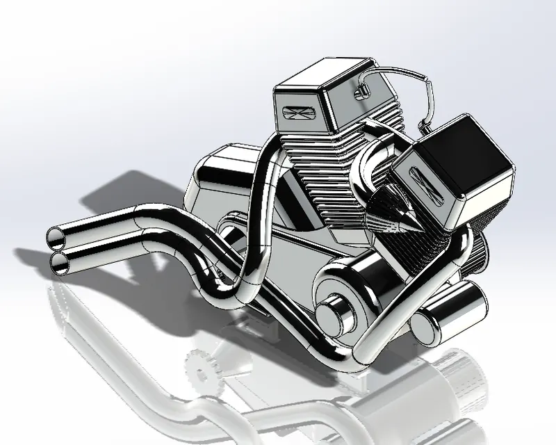
The engine is the powerhouse of the American chopper this is attached to the chassis. A side view of an American chopper is inserted as a sketch picture.The main components of the engine like the cylinders, the cylinder head, the crank case the pulley from engine to gearbox and the chain sprocket are Modelled in SolidWorks . We start with the crankcase,Then the gearbox , Then the front cylinder ,The rear cylinder is actually mirrored from the front cylinder and is combined to the rest of the engine. Later modeled the sprockets for the drive chain and pulleys that transfer power from the engine to the gearbox etc are modeled.Fillets are applied to the edges to make them looking smooth.Later material is applied for the engine is chrome metal.
⦁ Sketch Picture
⦁ Lines Circles
⦁ Constraints
⦁ Extruded Boss/Base
⦁ Revolved Boss/Base
⦁ Linear Pattern
⦁ Circular Pattern
⦁ Chamfer
⦁ Mirror
⦁ Combine
⦁ Projected curve
⦁ Composite curve
⦁ Split
⦁ Appearance
Gas Tank
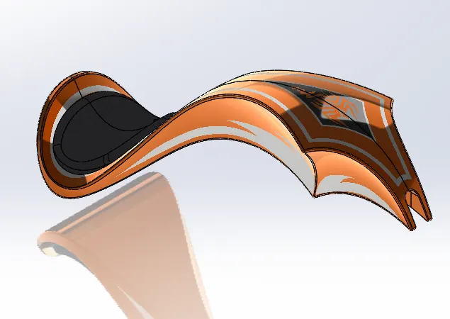
First insert a sketch picture in the sketch then use the splines to create a geometry often the tank . Initialy two sketches are made on two perpendicular planes and a sweep feature is used to produce a surface.Other surfaces are created by using splines and loft and boundary fill features .The different surfaces thus created are joined by using the knit feature.Finally a closed surface body is created and then converted into a solid body .The material applied surface of the tank is Siena.At last the solid bodies again made hollow using the shell feature .The main features used to produce the gas tank are:
⦁ Sketch Picture
⦁ Spline
⦁ Swept surface
⦁ Loft surface
⦁ Boundary surface
⦁ Knit surfaces
⦁ Mirror
⦁ Surface trim
⦁ Projected curve
⦁ Shell
⦁ Fillet
⦁ Appearance
Oil Tank
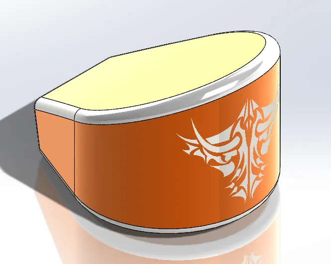
The oil Tank is made by extruding two sketches in two perpendicular directions.Then the two bodies thus generated are combined to take the common part out.We have given fillets on all the edges and then applied siena material on the surfaces of the tank. Only for the Fillets a white material is given as face selection.The features used for Oil tank are:
⦁ Extrude
⦁ Combine
⦁ Fillets
⦁ Shell
⦁ Appearence
Front Fork
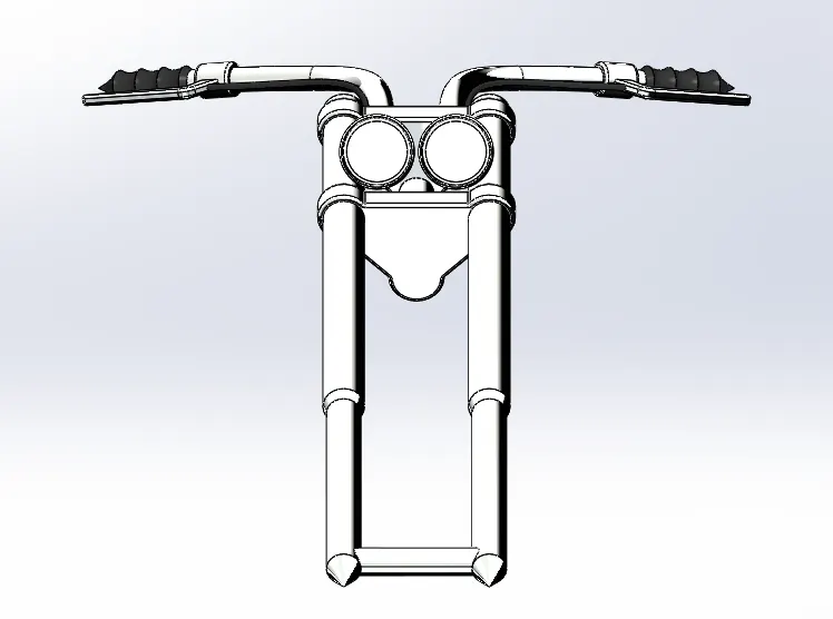
The front fork is made using the mirror feature mostly.Only half created initially and then is mirrored using the surface produced by the body itself. First the Fork tobes are made using revolve feature.Upper triple clamp is then made using extrude itself.The lower triple clamp is made using the linear pattern.Later made the axis of turning for the front fork.The triple clamps are made into a single body using combine feature. Later made the handle bars using the projected curve option.Same criteria is used for the cables.Glossy rubber material is applied for the handly grip surfaces and also for the cables.The headlamps are modeled as a component of the front fork itself.The features used for the front fork are as follows:
⦁ Sketch
⦁ Revolve
⦁ Extrude
⦁ Fillet
⦁ Linear pattern
⦁ Projected curve
⦁ sweep
⦁ Reference planes
⦁ Move/Copy
⦁ Mirror
⦁ Combine
Front Fender
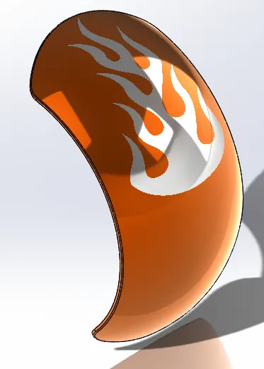
The front fender acts as a covering for the front wheels.It protects the rider from getting hit by waste thrown by the tire in wet conditions.It stays just above the front tyres.Mainly a revolve feature is used to produce the body.Then split feature is used to split the component and avoid the bodies not required.
⦁ Sketch
⦁ Revolve
⦁ Split
⦁ Fillet
⦁ Appearance
Rear Fender
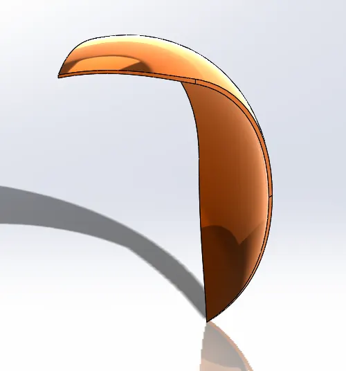
A similar kind of procedure for the front fender is used for the Rear Fender.The methodology is similar in both the components.The rear fender will position above the rear wheels which protect the rider from the dirt thrown by the rear wheels.The ,ain features that are used are:
⦁ Sketch
⦁ Extrude
⦁ Offset
⦁ Fillet
⦁ Appearance
Front Wheel
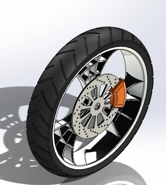
The front wheels supports the weight of the chopper in the front portion.It should be able to take all the static and dynamic loads that occur during operation.The Rubber should provide adequate grip in all conditions for safe and efficient manuering of the Chopper.The Hub and Rim are made using the revolve feature.They are connected by the spokes which are made bu extruding the sketch made using offset and convert entities.Brake rotor and brake caliper are then modeled . Tyre is made by using the revilve feature. Matte rubber is the material applied for the tyre.Chrome is the material applied for the hub, rim amd the spokes.Spokes are made using the circular pattern option.
⦁ Sketch
⦁ Sketch constraints
⦁ Revolve
⦁ Convert entities
⦁ Extrude
⦁ circulat pattern
⦁ extrude cut
⦁ Combine
⦁ Fillet
⦁ Appearance
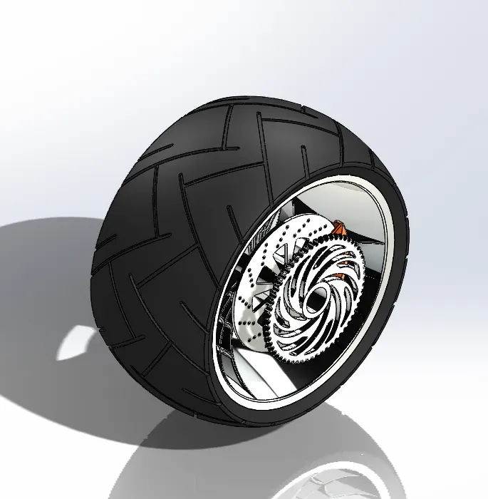
Rear Wheel
The Rear wheels supports the weight of the chopper in the rear portion.It should be able to take all the static and dynamic loads that occur during operation.The Rubber should provide adequate grip in all conditions for safe and efficient manuering of the Chopper.The Hub and Rim are made using the revolve feature.They are connected by the spokes which are made bu extruding the sketch made using offset and convert entities.Brake rotor and brake caliper are then modeled .The drive sprockets and the axle shaft are modelled . Tyre is made by using the revolve feature. Matte rubber is the material applied for the tyre.Chrome is the material applied for the hub, rim amd the spokes.Spokes are made using the circular pattern option.
⦁ Sketch
⦁ Sketch constraints
⦁ Revolve
⦁ Convert entities
⦁ Extrude
⦁ circulat pattern
⦁ extrude cut
⦁ Combine
⦁ Fillet
⦁ Appearance
Kickstand
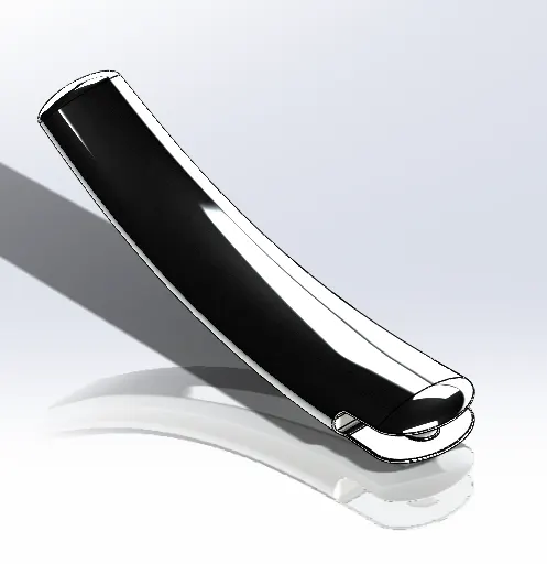
The Kickstand is used to supprot the chopper on the ground when it is not running.It takes the tilting weight of the chopper when it is on the ground.Kickstand is made by using the loft feature with two different sketches and a sketch that acts as the central panth.Then dome feature is used to provide curved body on the bothy ends.Split feature is used for producing the flat portion at the lower end of the kickstand.An extruded portion is made for connecting the kickstand with the chassis.
⦁ Sketch
⦁ Sketch constraints
⦁ Loft
⦁ Dome
⦁ Extrude
⦁ Fillets
Foot Pedal
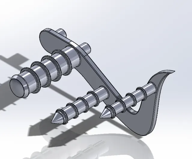
The foot pedal acts as a support for the legs of the rider.They also serves the purpose of rear brake and clutch in the chopper.The foot pedal sketch is made and is extruded.From the same sketch support for the legs are made bu extrude itself. The Connection between the pedal and the chassis is also made as extruded feature.
⦁ Sketch
⦁ Sketch constraints
⦁ Revolve
⦁ Convert entities
⦁ Extrude
⦁ circulat pattern
⦁ extrude cut
⦁ Combine
⦁ Fillet
⦁ Appearance
Transmission Belt
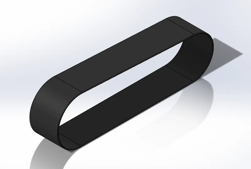
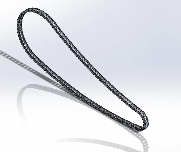
This transmission belt transmits the power from the engine to the gearbox The front pulley is smaller than the rear pulley .In this application a flat belt is used which is made of rubber and has nylon reinforcement .The Internal surface of the belt has square tooths on it that will lock into the tooths on the pully.The appearance applied is matte rubber .The features used to create the transmission belt are:
⦁ Sketch
⦁ Extrude
⦁ Offset
⦁ Fillet
⦁ Appearance
Chain
The chain transfer the power drom the front sprocket to the rear sprocket.The rear sprocket carries the power to the rear wheels and then onto the road.The front sprocket is smaller than the rear sprocket.This increases the torque available on the rear wheels.The Chain pins and the links are made using extrusion.These are then applied to curve driven pattern to produce multiple copies.The main features used are:
⦁ Sketch
⦁ Extrude
⦁ Blocks
⦁ Fillet
⦁ Appearance
⦁ Curve Driven Pattern
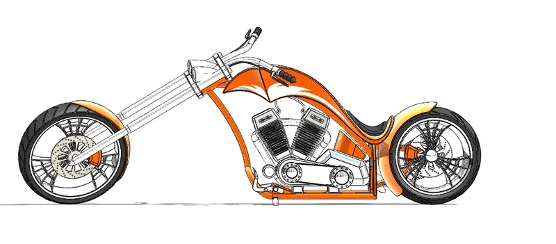
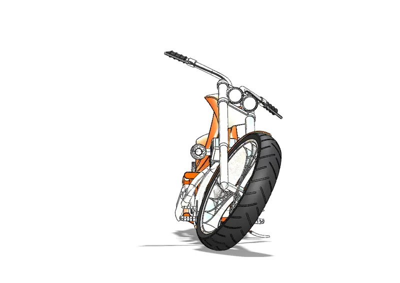
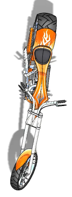
Assembly of the american Chopper
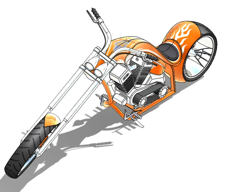
The components created as separate bodies areinserted into an assembly module in solidworks and then assembled into the fnal assembly.Mates are used to constrain and align the different components together.The chassis is fixed to the ground.All components are then attached to the chassis.
Rendering
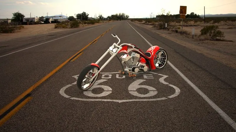
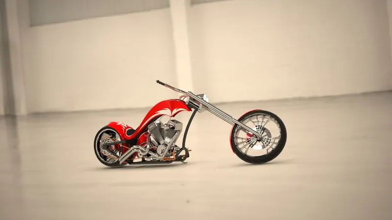
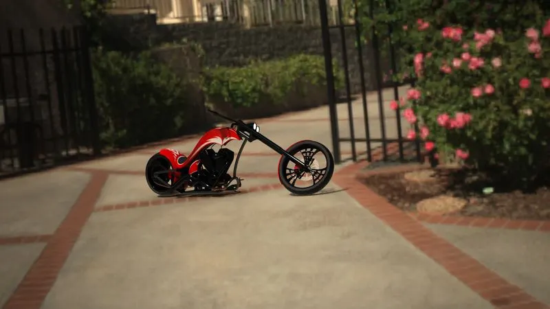
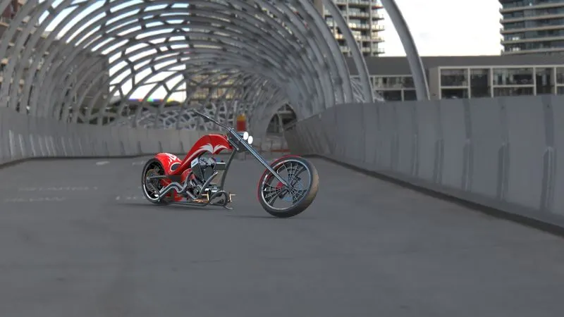
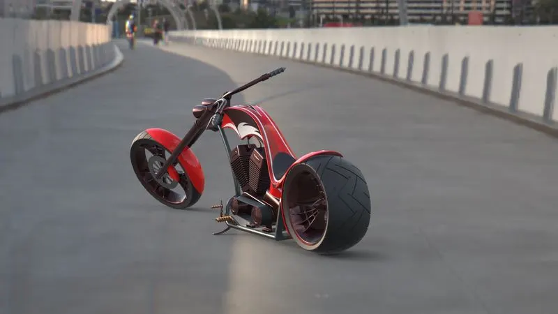
Rendering is referred to as the reakistic image that created from a CAD model.This is the image or animation that is closest to reality.We can add materials orappearences for the bodies.We can give a background and lighting and can add cameras for different view etc.
Rendering in Photoview 360
Rendering in Solidworks Visualize
Solidworks Visualize is a standalone rendering engine for solidwroks.It is available for those who have solidworks profwssional or premium.Here also we can add backgrounds,Environments,Lighting etc.The reality of the results that we get from visualize is amazing and the details are very good.Since it run independently of solidworks so a solidworks licence is not required.
Decals
A decal is a 2d image applied to a model.The 2-D image can be applied to the faces of the bodies.We have different projection methods available.We can add and edit decals in Photoview 360.
Cameras
Instead of basic views we can add Cameras at different points in space and can be adjusted to get a good view of the model.We can control the depth,focus etc of the camera.
Scenes
Scene can be defined as the backgroung that we give to the model.There are different backgrounds that are available in solidworks.This background is get reflected in the glossy parts of the model.
Lighting
Lighting can be added and adjusted in photoview and Visualize.We can add different lights such Ambient lights, point lights,directional lights, Spot lights etc.We can change the colour and illumination characteristics of the lights we given.
Conclusion
This course on American chopper model teach the basics of the solidworks workbench such as Sketching,Sketch constraints,Part modelling tools,Surface modelling,Assembly of different components,Rendering using Photoview 360 and Solidworks Visualize.