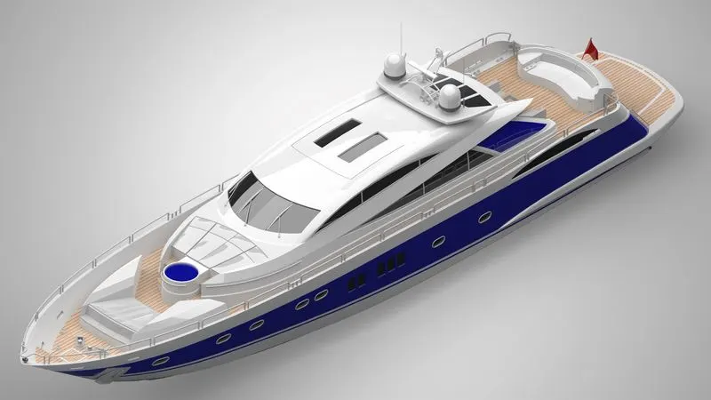
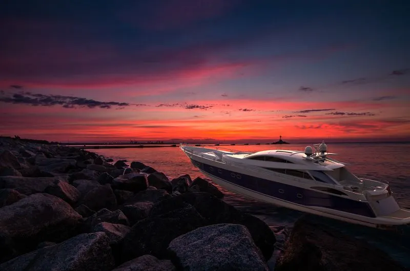
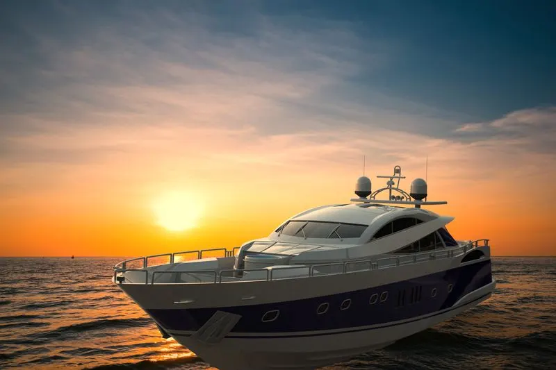
Radar Mast & Final Assembly of Yacht
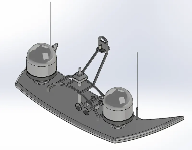
Radar Mast Views
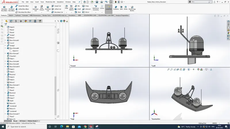
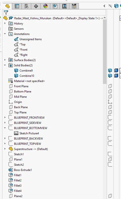
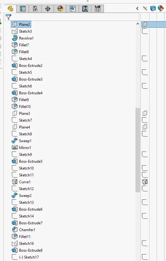
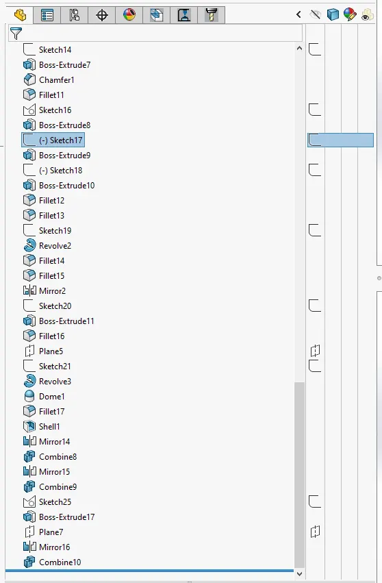
Radar Mast Model Tree
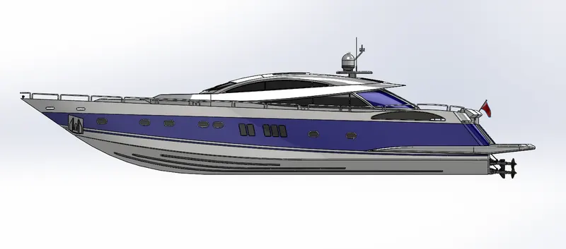
Yacht Assembly Views
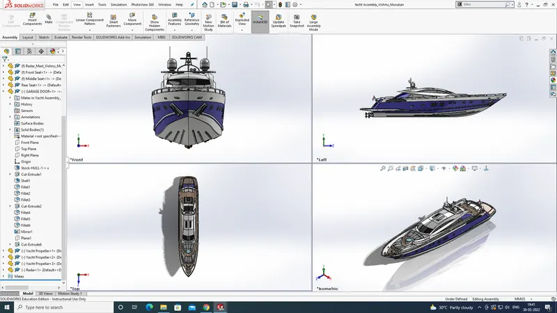
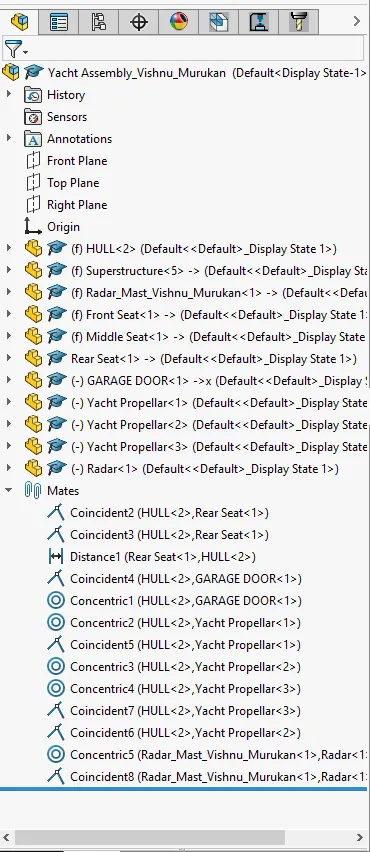
Yacht Assembly Model Tree
Project Report Of Modelling a Sunseeker Predator Yacht
Modelling and assembly of Sunseeker Predator Yacht In Solidworks
Introduction
In This project The modelling of different components and the assembly of therse components into a Predator Yacht is done in Solidworks.The Models are created individually and then imported into the assembly workbench to give mates and arrest the motion of components relative to each other.A base blueprint setup is created initially.This blueprint setup is then imported into other models to work as a reference for these components.The components That are required for the whole predator yacht are.
- Propellar
- Radar
- Hull
- Garage Door
- Front Seat
- Rear Seat
- Middle Seat
- Superstructure
- Radar Mast
All these components are modeled in Solidworks using appropriate tools and with the help of Surfaces and solid modelling tools.
Objectives
- Understand the Features in surfacing and solid modeling modules in detail.
- Understand the modelling of Different components and the criteria followed.
- Incorporation between Surface and Solid models.
- Assembling the different components and learn the Assembly mates in detail.
- Learn to render in Photoview and understand about Decals,environment,Lighting,Camera,Appearance etc.
- Rendering in Solidworks Visualize to make realistic models and understsnd the tools used in Visualize.
Design Approach
The two different approcahes that are used in CAD to make assembly models are:
- Top down Assembly
- Bottom up Assembly
Top Down Assembly
In top down assembly the model is start as an assembly itself.The components are models as parts in the assembly module.We can insert components that are already modeled.Here we can use other part entities as a reference.
Bottom Up Assembly
In bottom up assembly the components are modeled as separate part files in the part modeling workbench.These models are then imported into assembly workbench to give constraints.in this project bottom up approach is used.
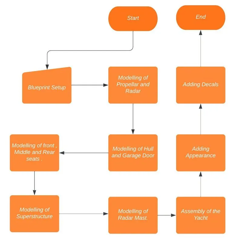
Here in this project the sketches for the yacht are available.These sketches are cropped to size and then arranged into a blueprint setup using the Sketch picture tool in solidworks.This is saved as Blueprint setup file.This Blueprint setup is inserted into other models as a reference.Then modeled the Radar amd Propellar.After that modelling of Hull of the Yacht is done.Blueprint setup is inserted and modelling has done mostly with surfaces.Then the surface model is converted into Solid model.After that Solid features are added.Then the modelling of front seat,rear seat and middle seat are done.These also utilize mostly surfaces.The flowchart of the design process is added below.
The main features that are used in this project are as follows.
- Sketch Picture
- Extrude Boss/Base
- Revolve Boss/Base
- Loft Feature
- Fillet
- Circular Pattern
- Appearance
- Surface loft
- Surface fill
- extrude surface
- Sweep surface
- extend surface
- Knit surface
- Surface trim
- delete face
- Sweep boss/base
- Linear pattern
- Mates
Sketch picture
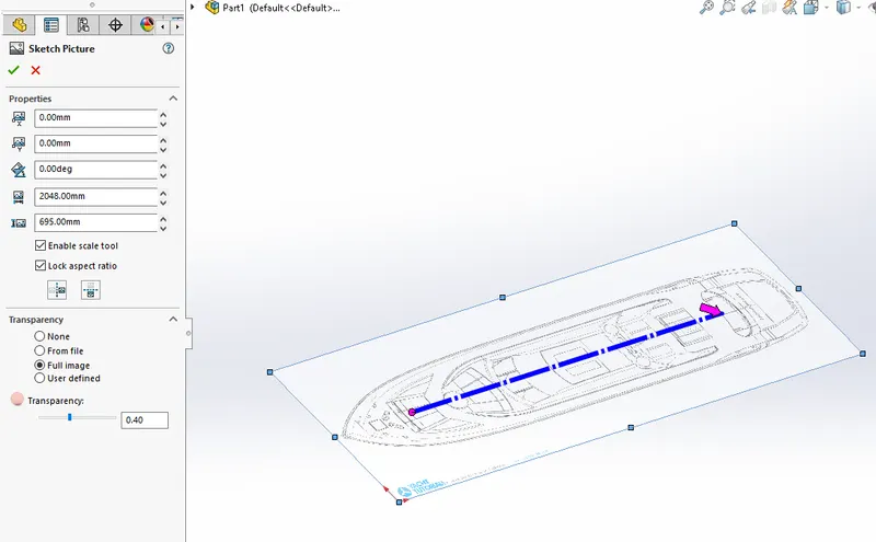
The sketch picture is a feature in the sketch panel to import external pictures into the model as references.These pictures can scaled and the aspect ratio and the position of origin also can be changed.The transparency is reduced to 40 percentage to better see the entities that we draw.
Extrude Boss/Base
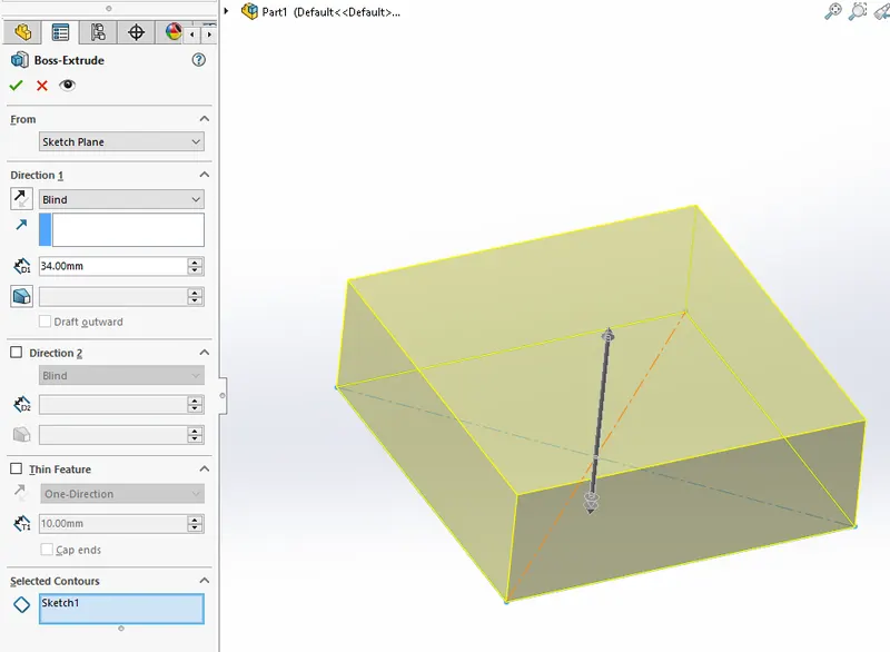
The extrude boss/base feature is used add thickness to a sketch.The direction of adding thickness can be given,the value of thickness to be added,draft ,thin feature etc can be added in this feature.This feature is used a lot in this project to model the different components.
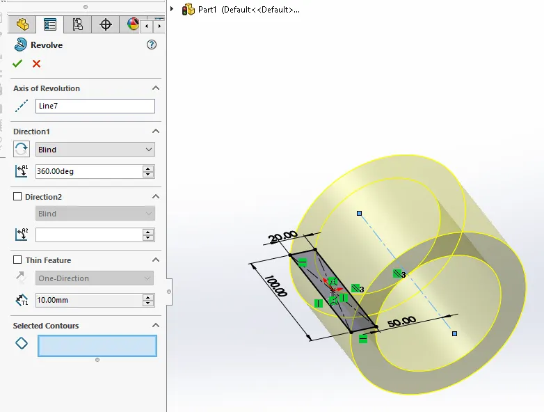
Revolve Boss/Base
This feature is used to create the solids of revolution.The half sketch is created with an axis of revolution.we can control the angle of revolution in both direction.
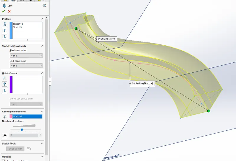
Loft Feature
This feature is used to create a solid with different cross sections at different planes.The path connecting the different cross sections can be controlled.
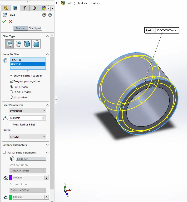
Fillet
Fillet is used to round off sharp edges to give a smooth finish for the edges.This gives a good appearance.This feature will add or remove material as per the edge alignment with the surrounding solids.
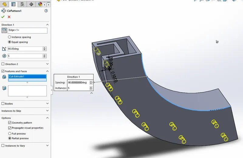
Circular Pattern
Circular pattern feature is used to generate multiple copies of a feature or bodies or faces in a circular path.The number of copies,The angle between copies etc can be controlled.
Appearence
Appearence feature is used for giving colours and patterns for solids,surfaces or features.We can give the RGB code for the colours to be given.
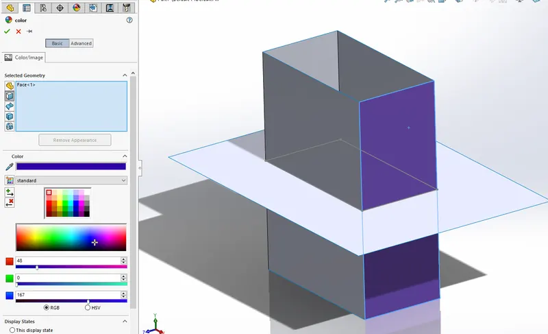
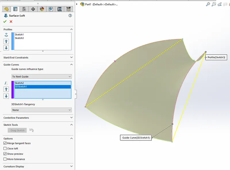
Surface Loft
The surface loft feature can be used to form a surface with different cross-sections.The path connecting the different crosssections can be defined.The guide curves feature is used for controlling the boundary of the surface.
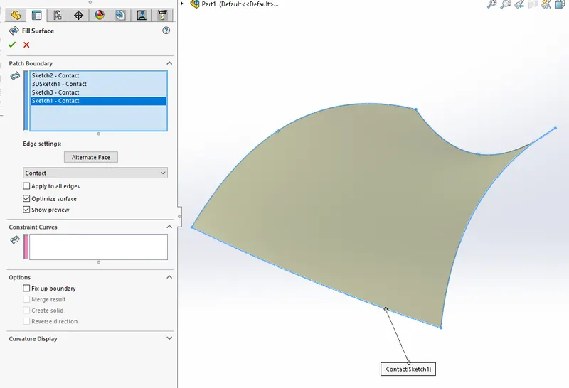
Surface Fill
Surface fill feature is used to form a surface from different sketches which together forms a closed figure.
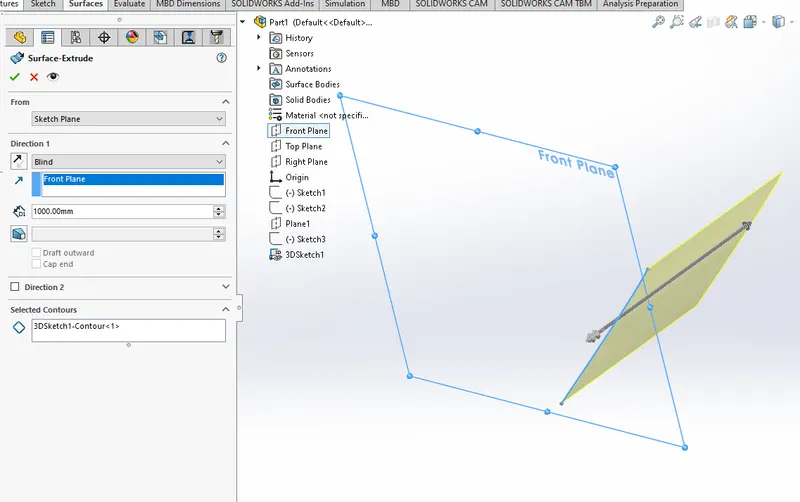
Extrude Surface
The extrude surface feature is used to produce surface from a sketch with giving a direction and a length of extrusion value.
Sweep Surface
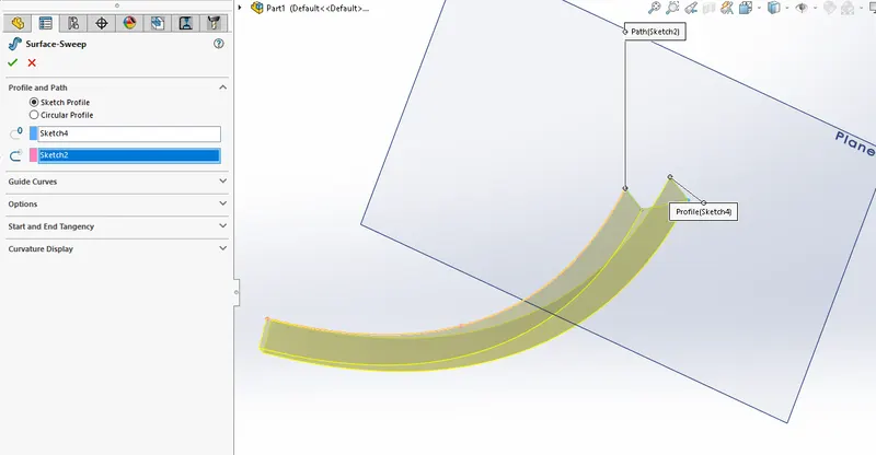
The sweep surface feature is used to produce a surface with a profile which flows along a path.
Extend Surface
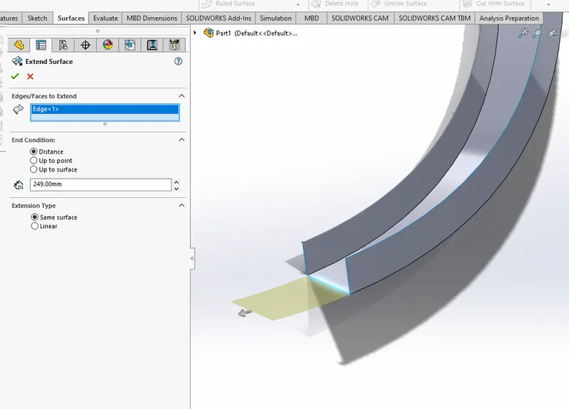
The extend surface feature is used to extend a surface to prescribed value along the same surface curvature or linear.
Knit Surface
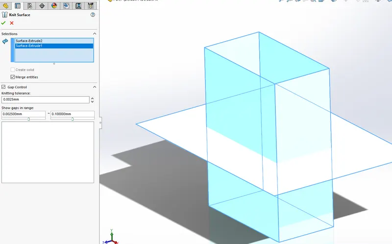
Knit surface feature is used to combine two surfaces together into a single surface.There should not be any gap between the two surfaces for the knit feature to work.Knit feature is used throughout in this project to form surface without any gap.
Surface Trim
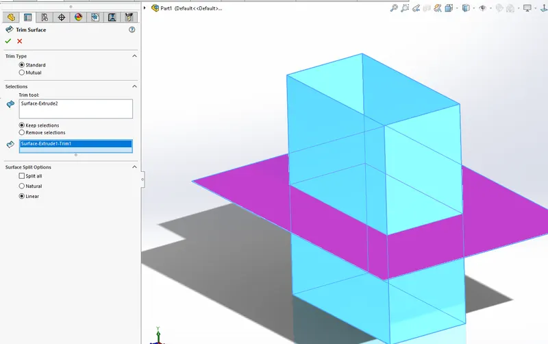
Surface trim is a feature which can be used to remove a surface part which cuts another surface.we can control which is the part to keep and which to remove.
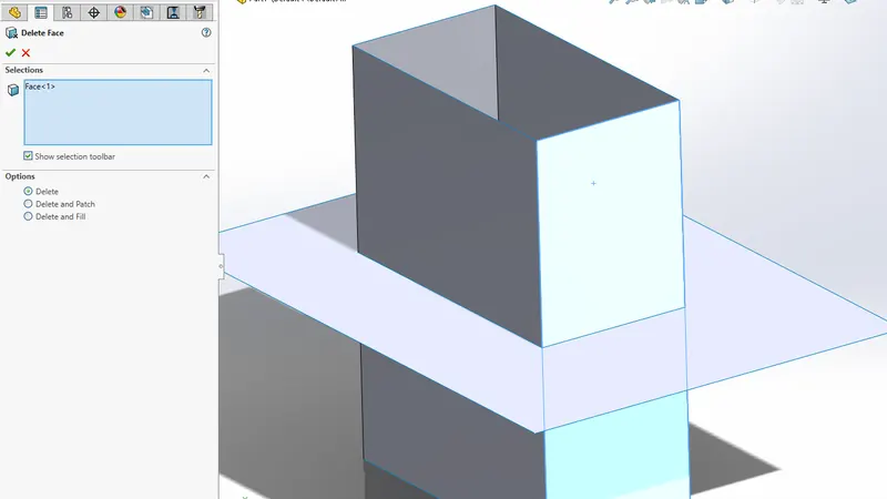
Delete Face
The delete face feature is used to fully remove a face.If the face of asolid is deleted remaining will become a surface.
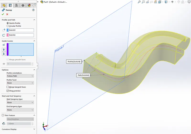
Sweep Boss/Base
This feature is used to form a solid body which has a profile which flows along a path.The path and the profile are drawn as different sketches and are need to be coincide with each other.
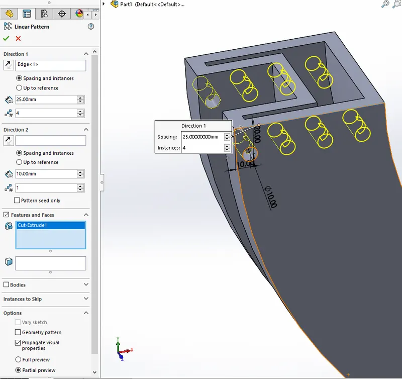
Linear Pattern
Linear pattern is similar to circular patter.This feature produce multiple copies of the Body,Feature,or faces that are selected along a particular direction.
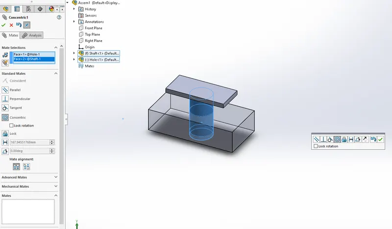
Mates
Mates are used to give relation between the different components.The faces,points,edges etc of one body can be related to another bodies corresponding entities.This forms an assembly.We can control select two entities and let off the control button to give mates instantly.
The main components that the Sunseeker Predator Yacht has are as mentioned in the introduction and are explained below in detail.
Propellar
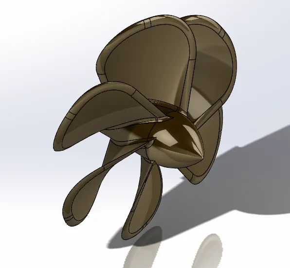
As the name implies the propellar propells the yacht forward.The engine is connected to the propellar through a gearbox and a clutch.The propellar rotates to induce flow of water past it.this produce a thrust.The Steeing is done by Rudders that are persent just before the propellar.The rudder can be turned to induce steering.This is mainly modeled using revolve and loft feature.Fillets are added at certain edges.Colour is added as material.The main features used are:
- Revolve
- Loft feature
- Fillet
- Appearance
Radar
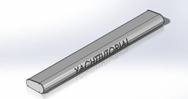
Radar is the component which serves as a communication for the captain.this enables the captain to know what are the other vessels around him in his vicinity.The Main body is extruded and the hex allen bolts are given as sketch pattern.The Text is added as an extruded cut which is offset from surface.The main features used are as follows:
- Extrude Boss/Base
- Fillet
- Sketch Pattern
- cut extrude
Hull
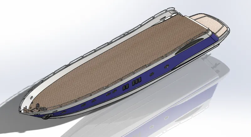
Hull is the base of the Yacht.This touches the water and enables the floating of the vessel.Mainly surface features such as loft,Fill etc are used fot the body.the surface is closed with using other features and made into a solid usingthe knit feature.
The features used are as flollows:
- Extrude surface
- revolved surface
- Lofted Surface
- Fill surface
- Knit surface
- Trim surface
Garage Door
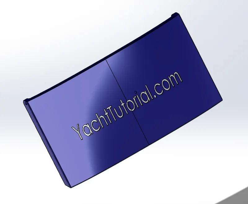
The garage door closes the cavity of the hull.this forms a closed cavity where we can keep other things like car or bikes.This component is created from the hull body as a result of the split command.The cut body is exported as another body.this is then cut extruded shell is applied.Fillets are applied.Then given a blue appearence also for the whole body.The feature used are:
- Split
- Extrude cut
- Shell
- Fillet
- Mirror
- Appearence
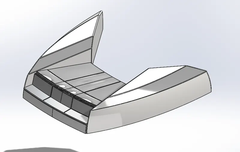
Front seat
The front seat is modeled mostly by using surfaces.Different seat pads are extruded and revolved.dome feature is applied on the top portion.Features used are:
- Sweep surface
- Fill surface
- Revolve Boss/Base
- Extrude Bos/Base
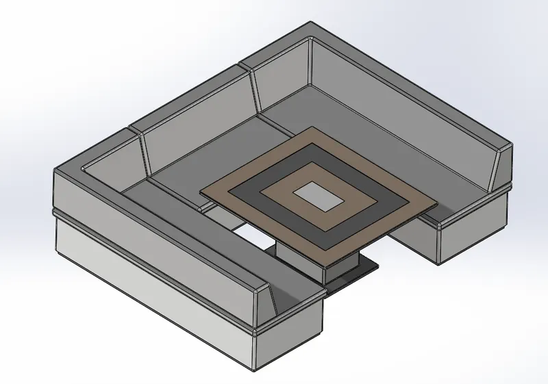
Middle seat
The middle seats are produced mostly as Extrude features.Mirror command is used to produce the other half of the seat and are combined into a single body.The seat cusions are made as separate solids.A table is also modeled using the extrude feature mostly.Fillets are applied at certain edges and colours are given for different faces as appearence.The features used are as follows:
- Extrude Boss/Base
- Surface Offset
- Fillets
- Mirror
- Extrude cut
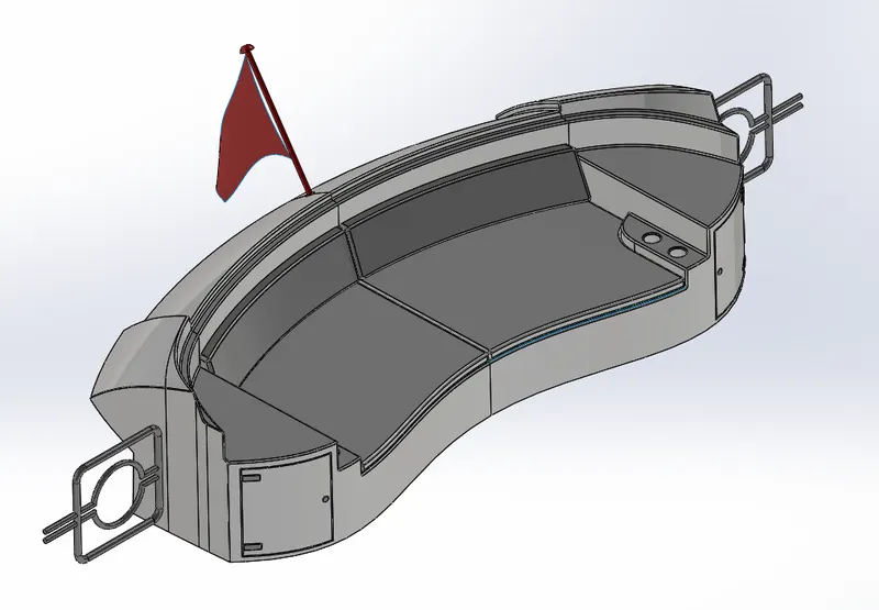
Rear seat
The rear seat is modeled mostly as surface.These surfaces are knitted together to produce a final solid.The flag is also modeled as a component inside the rear seat.Extrude boss feature is used mostly to produce the seat cusions.Half of the seat is modeled and mirror feature is used to mirror the other half and are combined together.The commands used are:
- Extrude surface
- Sweep surface
- Surface fill
- Knit surface
- Ruled surface
- Surface loft
- Extrude Boss/Base
- Revolve Boss/Base
- Fillets Mirror
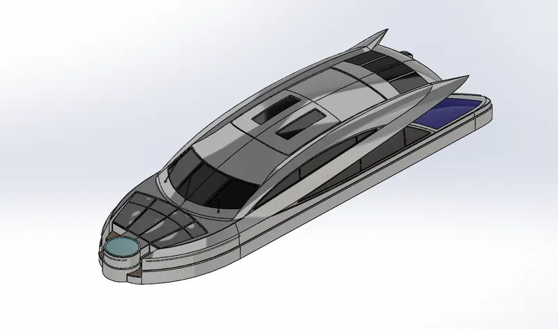
Superstructure
This is the space where the captain is sitting.Here also the controlling mechanisms are also situating.This is the main control centre of the Yacht.The body is created as surface from the blueprint reference.The surfaces are made into a closed body usng the knit feature and are then mirrored to produce the other half.Appearance are applied for the appropriate faces.The main features used are:
- Sweep surface
- Extrude surface
- Loft surface
- Fill surface
- Ruled surface
- Extend surface
- Knit surface
- Trim surface
- Boss extrude
- Revolve Boss/Base
- Fillets
- 3D sketch
- Sweep
Radarmast
This is where the communication mechanisms for the yacht is situating.The radar mast situates on the roof of the superstructure.Solid bodies are created using extrude boss/Base.Then applied fillets.The lighting fixture frames are modeled usng sweep feature and are then patterned linearly.Revolve is used to produce the bulb on the top.antennas are also modeled as extrude features.The commands used for this component are as follows:
- Extrude Boss/Base
- Revolve
- Sweep
- Linear pattern
- Shell
- Mirror
Assembly of Sunseeker Predator Yacht.
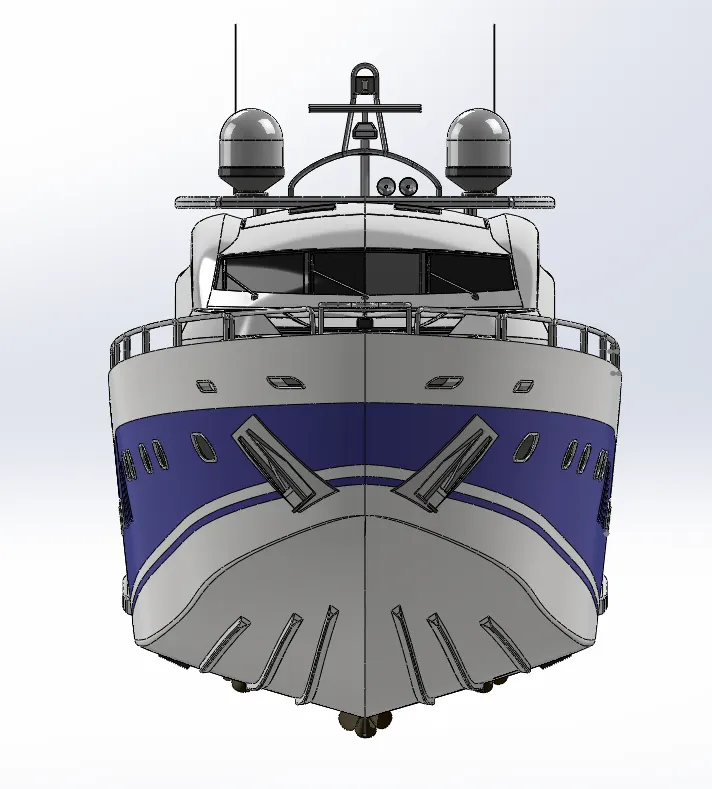
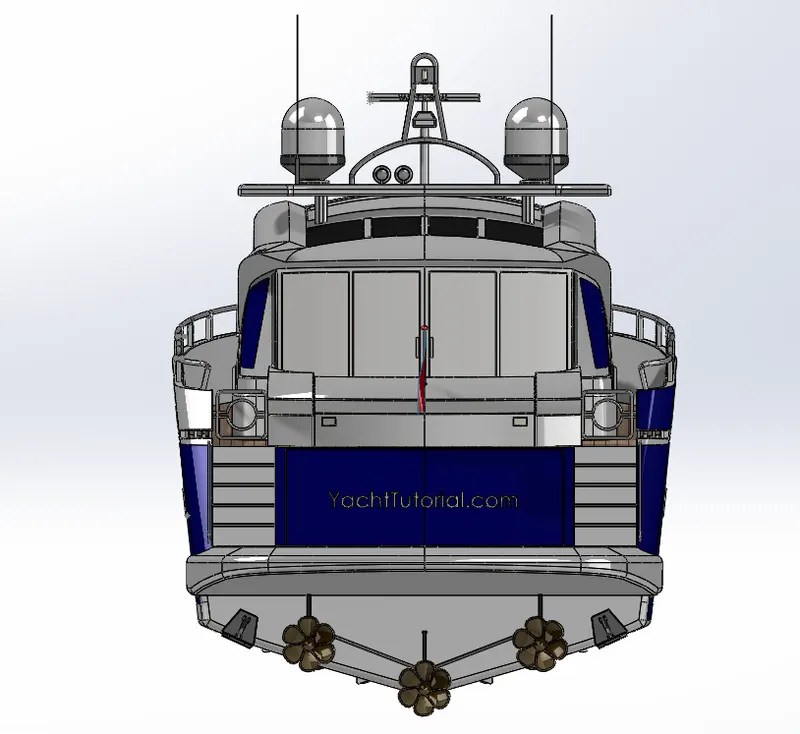
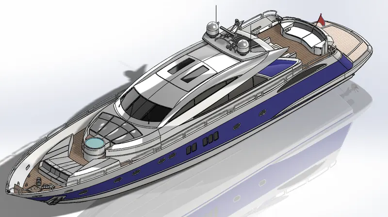
The components above mentioned are then assembled in the assembly module in solidworks.First imported the Hull into the assembly.Then the Superstructure is imported.Since all the components are modeled using the same blueprint reference, The components fit in the correct place instantly.then Radar mast,Front seat, and middle seat are imported.The rear seat is assembled with the hull using the coincident and distance mates.The Radar has given concentric and coincident mates.
Side View of Yacht
Yacht Front View
Yacht Rear View
Yacht Isometric View
Rendering
Rendering is the procedure of creating realistic views in CAD packages.In solidworks the rendenring can be done in mainly two rendering engines
Photoview 360 and Solidworks Visualize
Photoview 360
The photoview 360 is the inbuilt render engine for solidwroks.The models can be edited directly in solidworks itself.We can add Decals,Environment,Lighting etc.The camera that we add in the modeling workbench can be directly added for rendering.Decals can be added on surfaces and the scales can be adjusted.The environments can be changed for different lighting.Camera can be added in the modelling workbench itself and the camera angle,depth area etc can be adjusted.
Solidworks Visualize
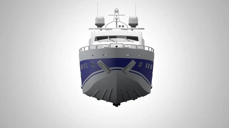
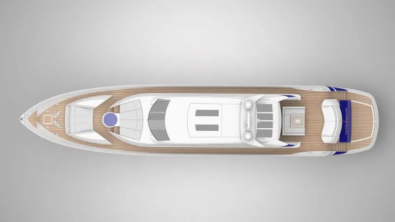
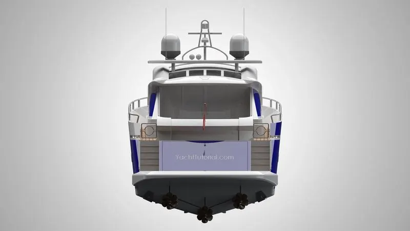
Solidworks visualize is a standalone Render engine for Solidworks.This works independent of Solidworks so there wont be any licence issues when doing the rendering.In visualize also we can change the Environment.Plates can be added as background images.Camera views can be changed.Views can be changed from perspective to orthographic.Below shows the rendered images of the Yacht.
Front View Render
Top View Render
Rear View Render
Isometric View Render