Aston Martin ONE-77 Challenge-11 (Project)
Modelling Aston Martin One-77 In Solidworks
Introduction
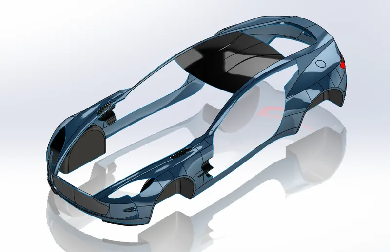
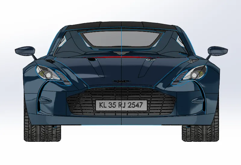
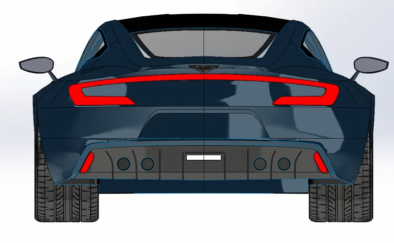
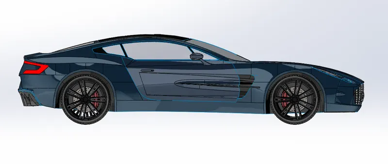
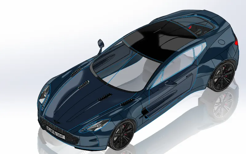
In this project the modelling and assembly of Aston Martin One-77 car is done. As the name suggests only 77 of this car is ever built .So it is a very rare piece of engineering .The Aston Martin 177 is a 2 door 2 seater flagship Grand Touer.It has full carbon fiber monocoque chassis and a 7.3 litre engine with 4 valves per cylinder which produces a maximum power output of 750 HP To 7500 rpm and 750 Newton meters of torque at 5000 rpm .So this is one of the most powerful naturally aspirated engines ever built .This is a naturally aspirated V12 engine .The engine is mated to a six speed automated manual transmission which is developed by graziano transmissioni.The modeling is mostly consists of surfaces which are produced using surfaces workbench in SolidWorks .The whole car body is a single surface with additional surfaces for Doors the engine hood etc.The whole body of the car is modelled using surfaces utilizing the surface features like extrude surface, loft surface, boundary surface, extend surface, ruled surface surface trim etc .The basic components of the car that are modelled in soldworks are given below.
⦁ Blueprint Setup
⦁ Roof
⦁ Side
⦁ Fenders
⦁ Rear
⦁ Front Bumper
⦁ Hood,Windows,Doors
⦁ Front Wing
⦁ Grille
⦁ Lights
⦁ Wheels and Brakes Assembly
⦁ Aston Martin Emblem
⦁ Assembly of the whole model.
⦁ Photorealistic rendering
Objectives
⦁ To Model the Aston Martin One-77 in solidworks
⦁ To be familiar with the workflow of modelling a car in solidworks
⦁ To study about the surface features in solidworks and apply it to real world applications.
⦁ To create real world inspired rendering in solidworks visualize and understand the tools.
Desigh Approach
In Part modelling there is mainly two different approaches that are followed:
1.Surface modelling
In surface modelling the component to create starts as a suface and are not solids.These surfaces can be later converted into solids to further assemble.Using surface modelling comples surfaces can be created that are quite hard to model using solid modelling.
2.Solid modelling
The solid modelling is a modelling criteria in which the body is modelled as a solid itself.The solid modelling features in solidworks are quite elaborate and easy to work with.
The different Design criterias that are used for assembly are as follows.
1:Bottom up Approach
Here each part of an assembly is modelled separately in apart modelling module and are saved as part files in the file path.These parts are later inserted into an Assembly workbench and are assembled together using different relationships between each other.In this project a bottom-up approach is followed.
2:Top-Down Approach
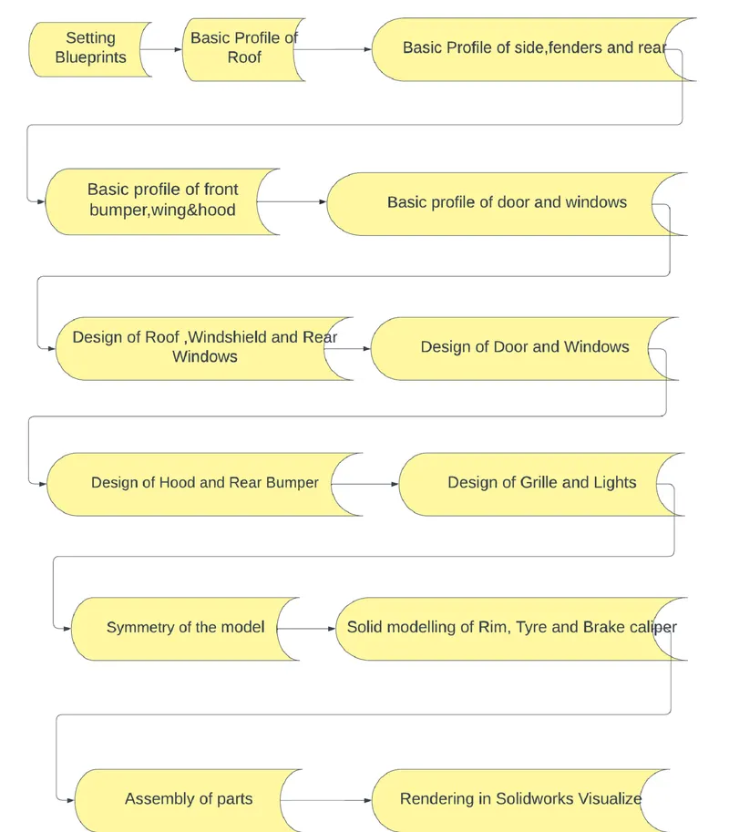
In top-down Approach the part starts as an assembly itself.The individual parts are modeled as individual components within the assembly workbench.One advantage of this method is that we can refer other bodies features in modelling a different component.Design criteria followed in this project is showed in the chart below:
The Main Features that are used in this Project are as follows:
- Sketch Picture
- Projected Curve
- Boundary Surface
- Lofted Surface
- Ruled surface
- Extend surface
- Extrude surface
- Filled surface
- Knitted surface
- Split line
- Split
- Delete face
- Delete body
- Offset surface
- Move/Copy Bodies
- Cut with surface
- Thicken
- Extrude Boss/Base
- Revolved Boss/Base
- Revolved cut
- Swept cut
- Linear Pattern
- Circular Pattern
- Curve driven Pattern
- Fillet
- Combine
Sketch picture
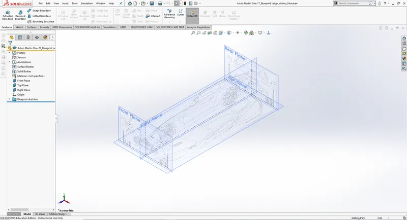
Sketch picture is a feature inside the sketching environment where we can insert images of the bodies we are going to model as per the dimensions and scaling.this picture can be used as a reference for the modelling.
Project Curve
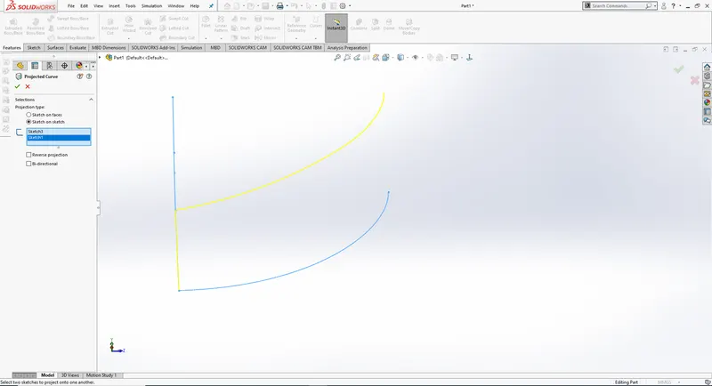
This is a Tool which can be used to create complex curves from simple sketches on two perpendicular planes.This tool can also be used to project a sketch onto a plane or a face of a model.
Boundary Surface
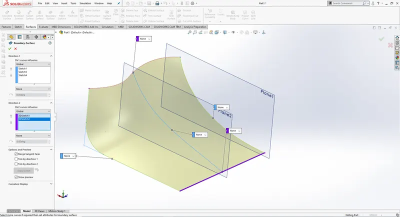
The Boundary surface is used to create surfaces passing through multiple sketches in two different directions.The first direction and second direction are to be selected continuously.We can add tangency conditions in all the sketches in the boundary surfaces.
Lofted Surface
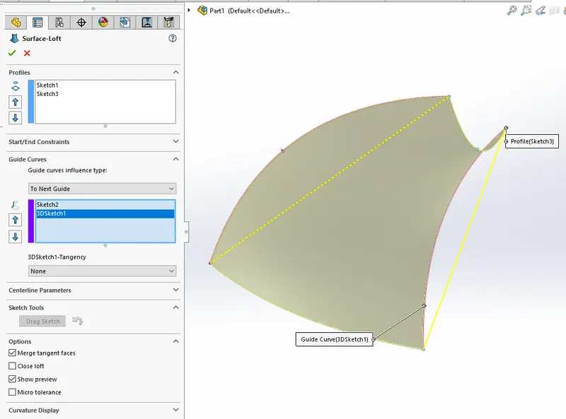
The surface loft feature can be used to form a surface with different cross-sections.The path connecting the different crosssections can be defined.The guide curves feature is used for controlling the boundary of the surface.
Ruled surface
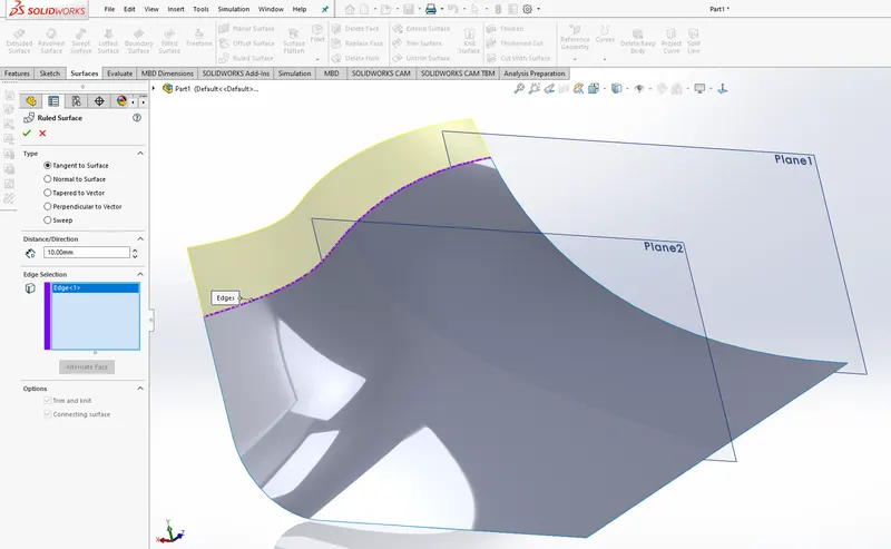
Ruled surface is used to extend the edges of already available surfaces in a given direction such as either normal to the surface,tangent to the surface or in a given direction.
Extend surface
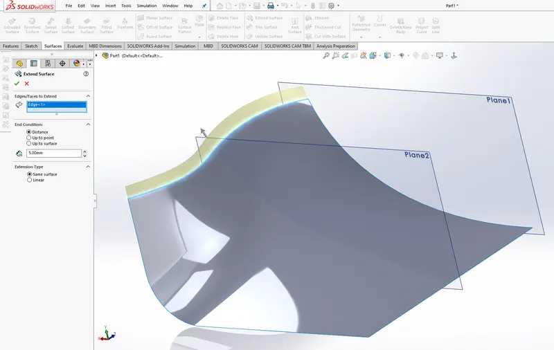
The extend surface is similar to the ruled surface but the surface can be extended only in a tangent direction or with same curvature.
Extrude surface
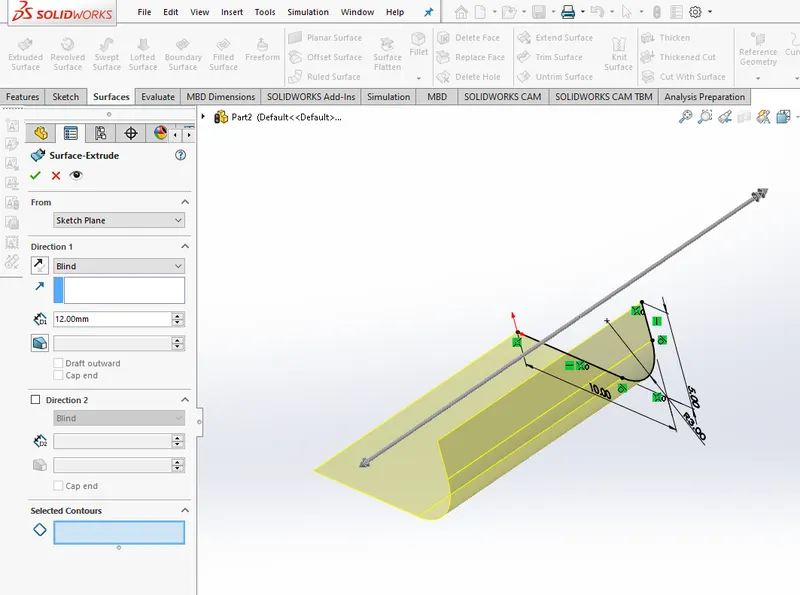
Extrude surface is used to extrude a given sketch,either closed or open into a surface in a perpendicular direction to the plane of the sketch.
Filled surface
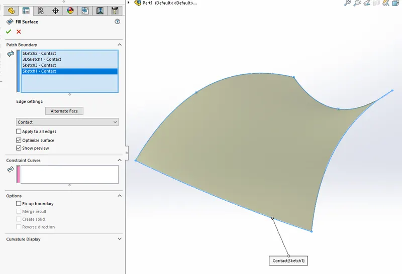
Surface fill feature is used to form a surface from different sketches which together forms a closed figure.
Knitted surface
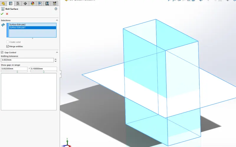
Knitted surface is used to combine two different surfaces which are connecting together into a single surface.
Split line
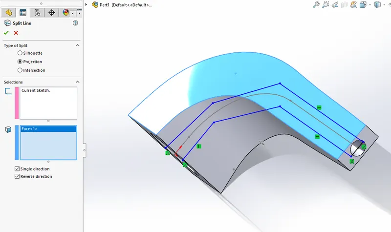
the split line tool is used to split the surfaces off parts. The split and be made by sketches of surfaces. We have to select the type of split as silhouette or projection and what is the sketch used for the splitting and also the face on which splitting is to be effected.
Split
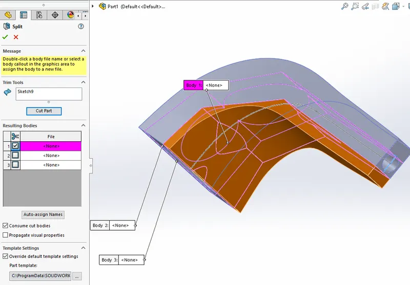
Split tool is a feature used to cut certain parts of bodies using surfaces or sketches etc. We can control which part of the body is to be removed and the removed part can be saved as an external part file. In the figure drawn below the cut is made by a sketch on the body which is ticked-on in blue colour in the detail window will be removed since the consume cut body is activated.
Delete face
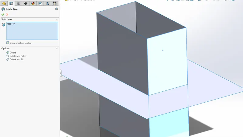
Delete face is used to remove a face from a surface or a solid body and converting it into a surface body.
Delete body
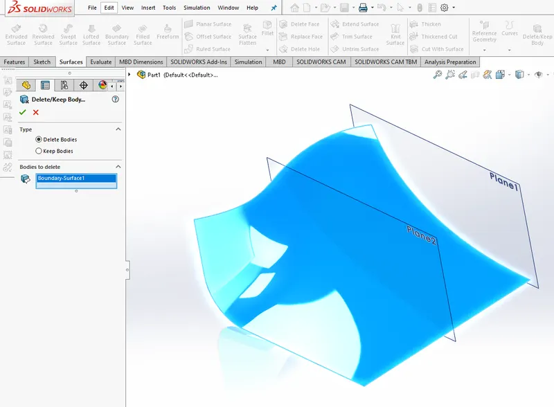
Delete body is used to delete a surface or solid body without affecting any of its dependent features.
Offset surface
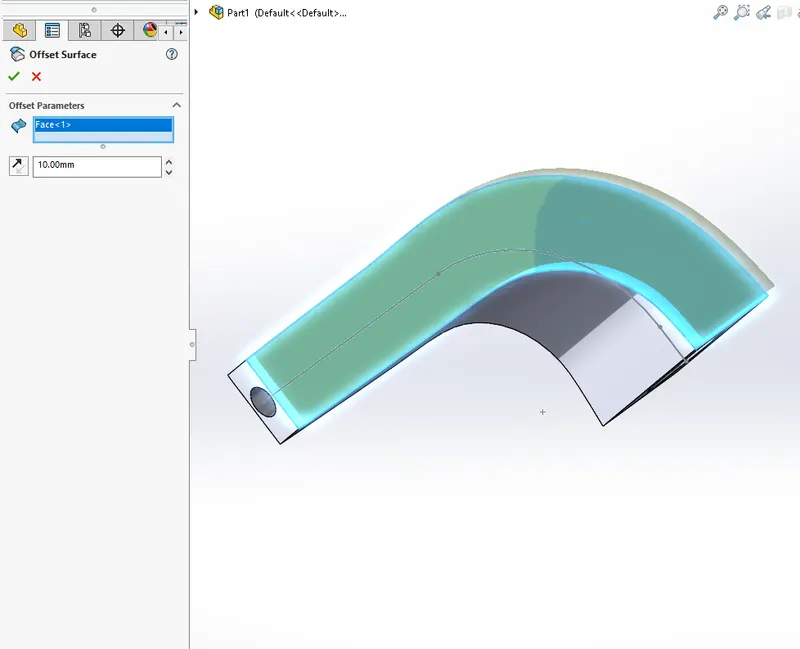
The offset face feature is used to do create a face which is offset from another face. This can also be created as a copy face which is a face at an offset of zero distance. We can later thicken the surface to produce a solid.
Move/Copy Bodies
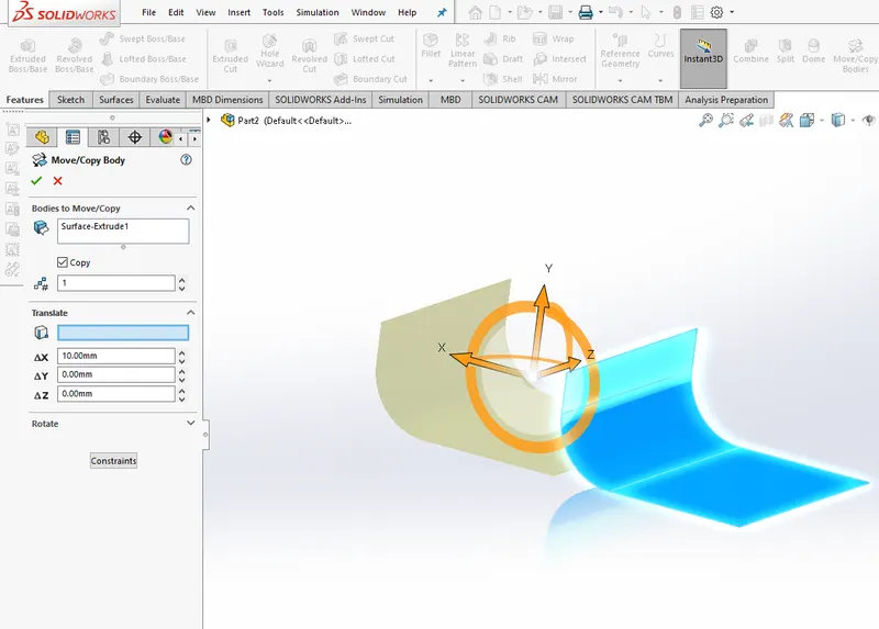
The move/Copy Bodies is a tool which can be used for translating or rotating surface or solid bodies in the model.
Cut with surface
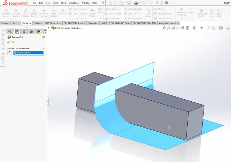
Cut with surface is a tool which can be used to cut a solid with a surface intersecting it through the intersecting face and remove one part of the body.
Thicken
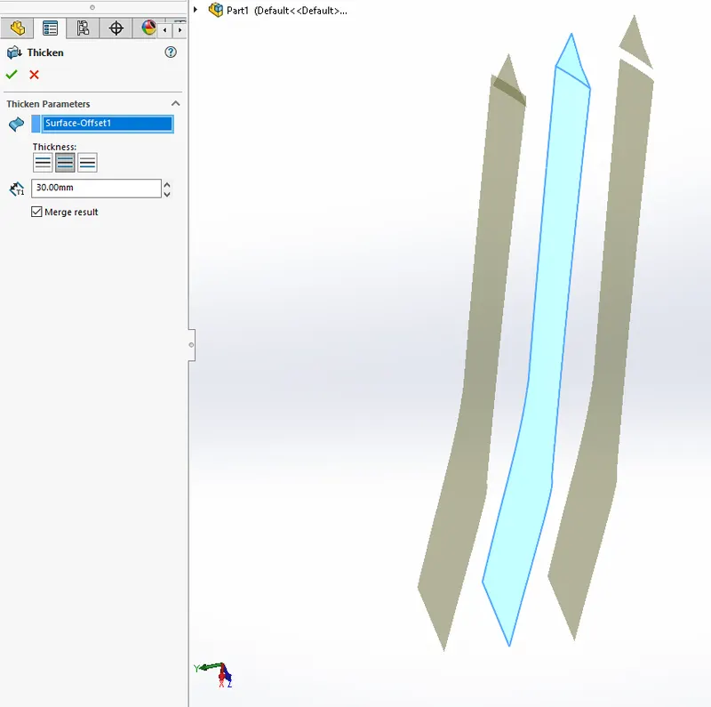
Thicken surface is used to add thickness to a given surface in a given direction.
Extrude Boss/Base
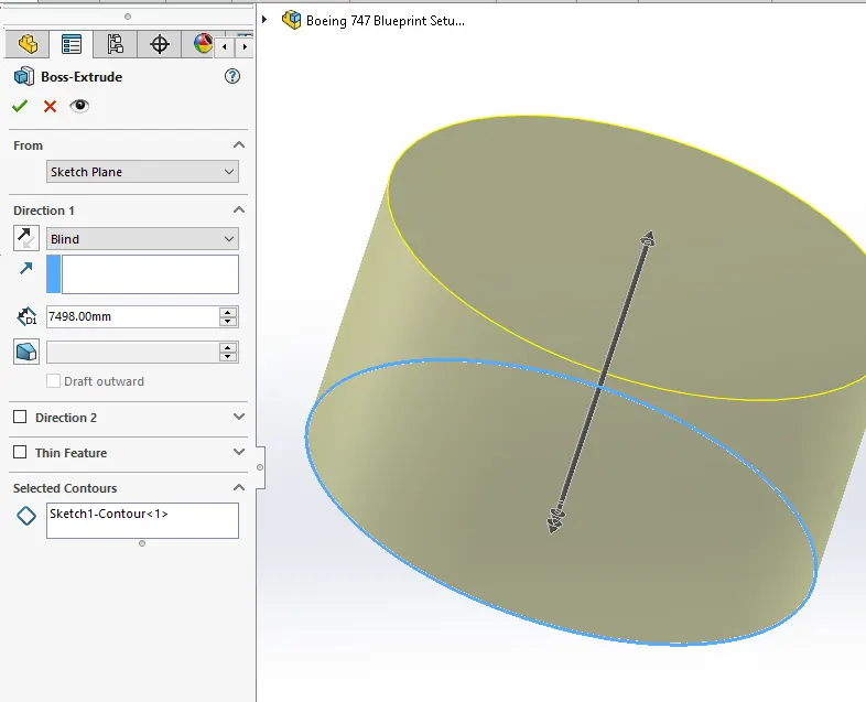
The extrude command in solidworks is used to give thickness to a sketch.If the sketch is closed then the resulting body will be a solid body,if the sketch is not closed it will give a thin feature extrusion where the resulting body has a thickness about the open sketch.
Revolved Boss/Base
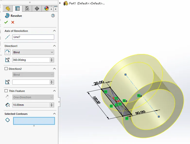
The Revolve boss/base is the tool used to make solids of revolution.The closed sketch is revolved about an axis of selection.
Revolved cut
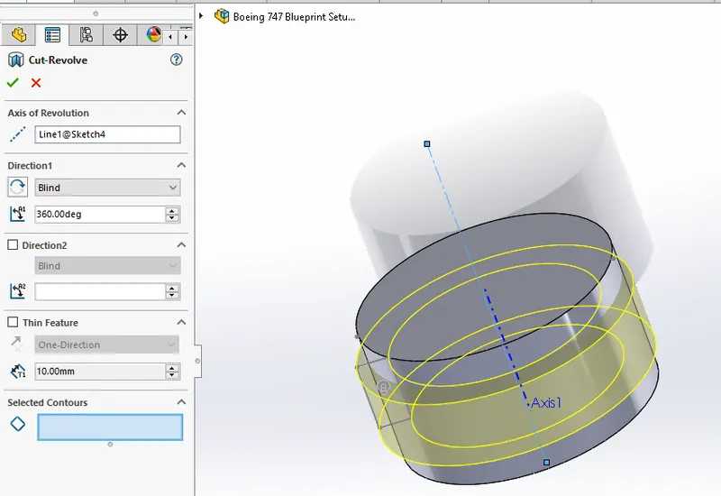
The Revolved cut is the material removal process similar to revolve boss/base.The procedure is similar to the boss operation and we need a closed sketch and an axis of revolution
Swept cut
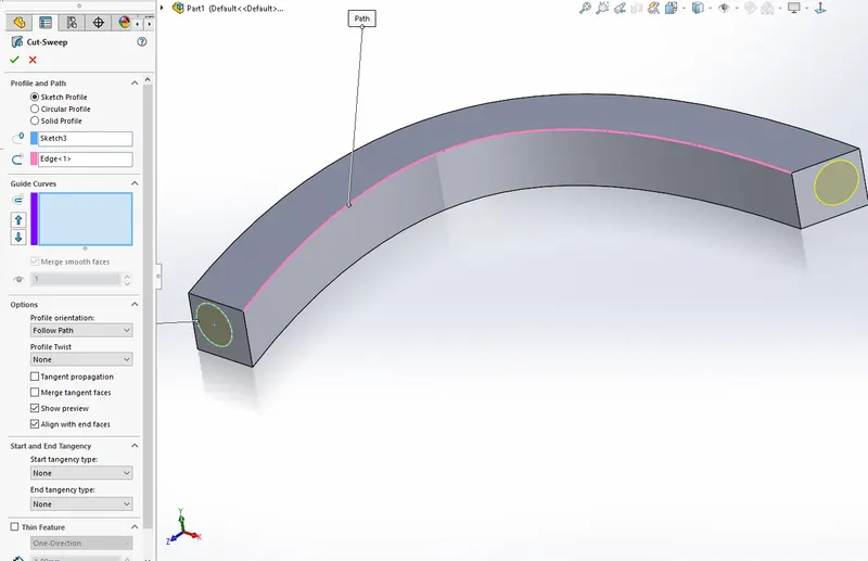
Swept cut is the material removal version of the Sweep boss/Base.A closed sketch and a path is required.The cutting part should intersect a body,otherwisw it will give error.
Linear Pattern
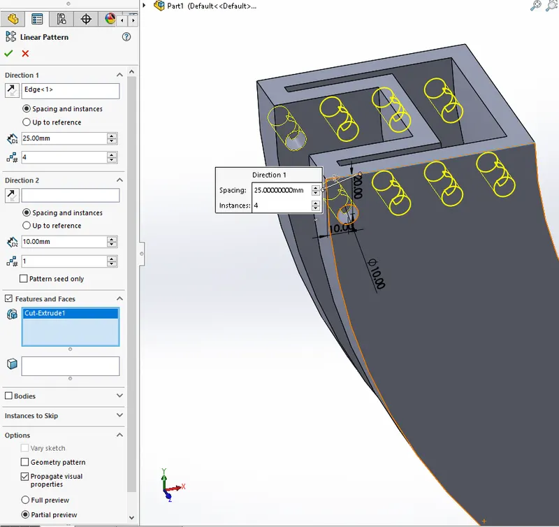
Linear pattern is similar to circular patter.This feature produce multiple copies of the Body,Feature,or faces that are selected along a particular direction.
Circular Pattern
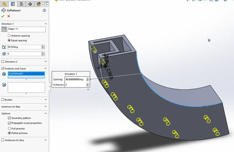
Circular pattern feature is used to generate multiple copies of a feature or bodies or faces in a circular path.The number of copies,The angle between copies etc can be controlled.
Curve driven Pattern
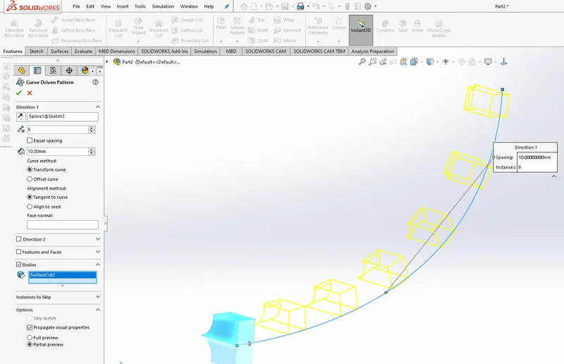
The Curve driven pattern can be used to make multiple copies of a given body/feature along a given sketch.
Fillet
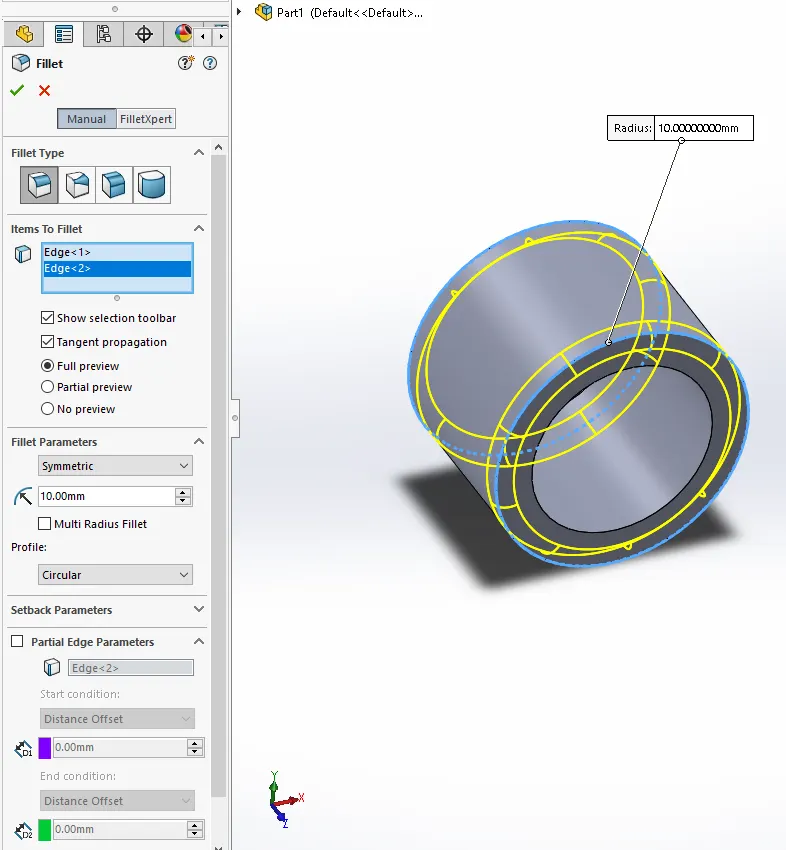
Fillet is used to round off sharp edges to give a smooth finish for the edges.This gives a good appearance.This feature will add or remove material as per the edge alignment with the surrounding solids.
Combine
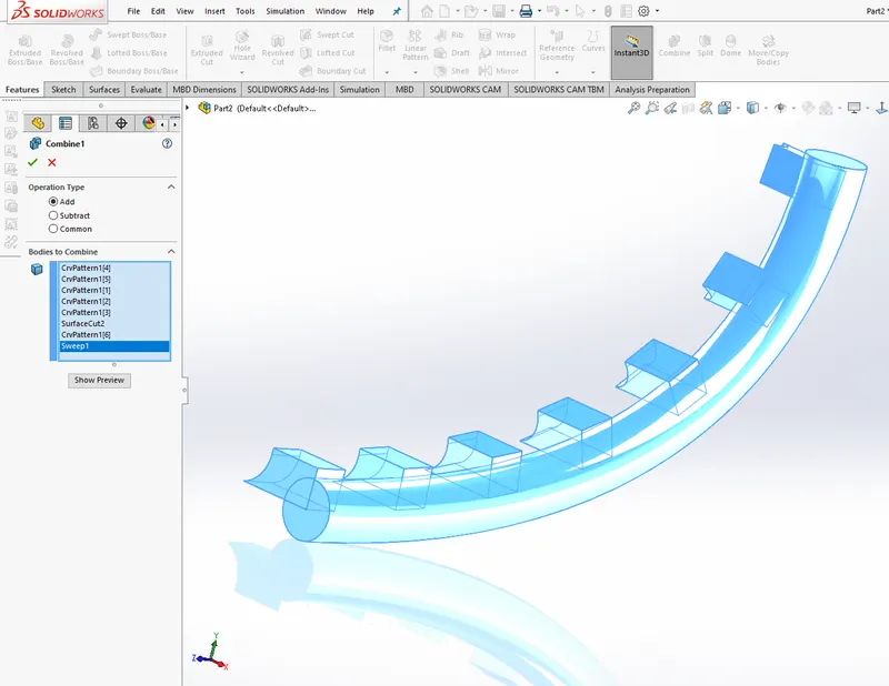
Combine tool is used to Add/Subtract/Intersect multiple bodies together giving new bodies of complex geometry.
Mates
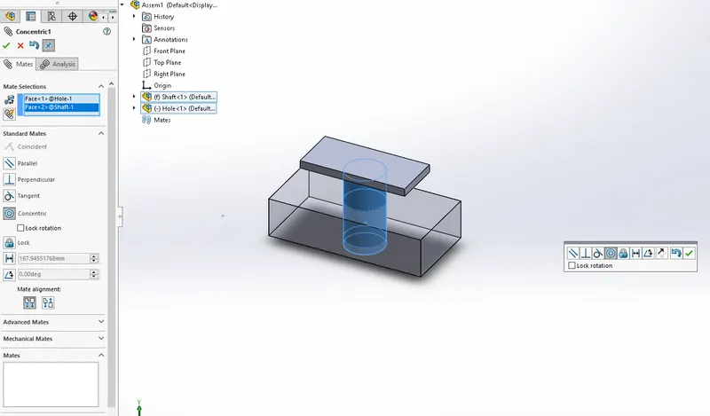
Mates are used to give relation between the different components.The faces,points,edges etc of one body can be related to another bodies corresponding entities.This forms an assembly.We can control select two entities and let off the control button to give mates instantly.
The Below mentioned components are modelled using the above mentioned surface and solid modelling tools:
Blueprint Setup
Blueprint setup acts as a reference for the modelling.The main features used are as follows:
- Sketch Picture
- Reference objects
Roof
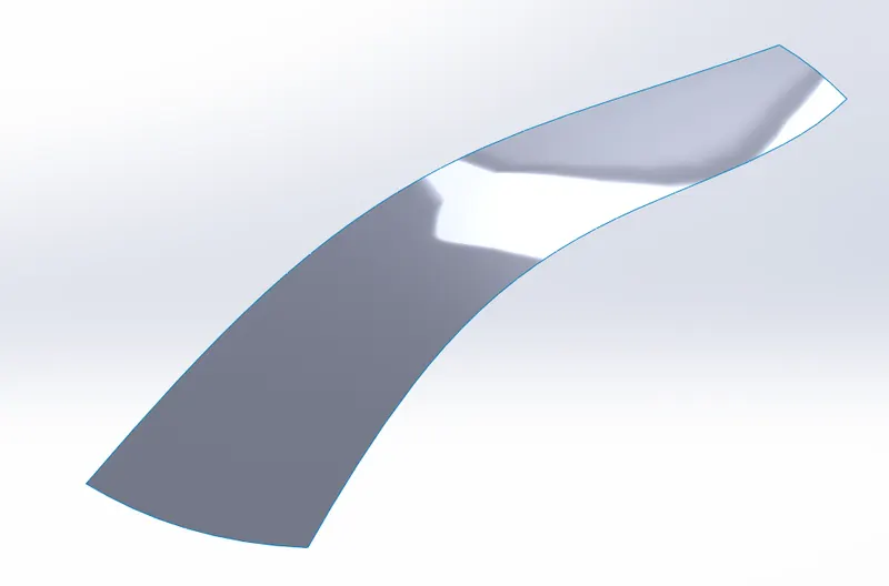
The roof is the top part of the car.Here the Windshield and Rear window are also modelled as a part of the roof itself.Later these features are to be removed.The features used are as follows:
- Projected Curve
- Boundary surface
Side
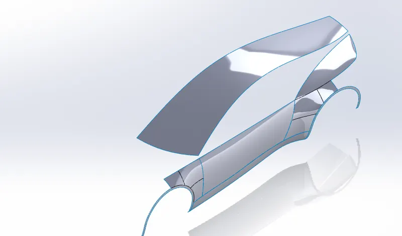
The side is the part of the door and the panels on the side of the car.The features used are as follows:
- Projected curve
- Extrude surface
- Surface trim
- Filled surface
- Boundary surface
Fenders
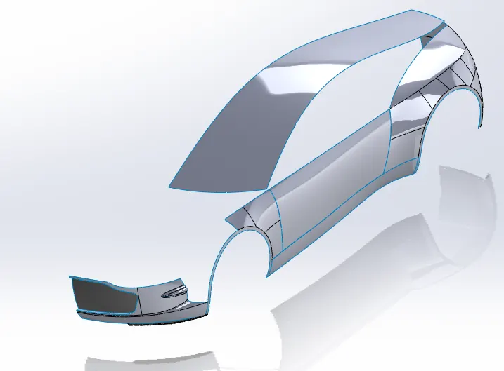
The fenders are the part above the Wheels.The features used for modelling are as follows:
- Projected curve
- Extrude surface
- Surface trim
- Filled surface
- Boundary surface
Rear
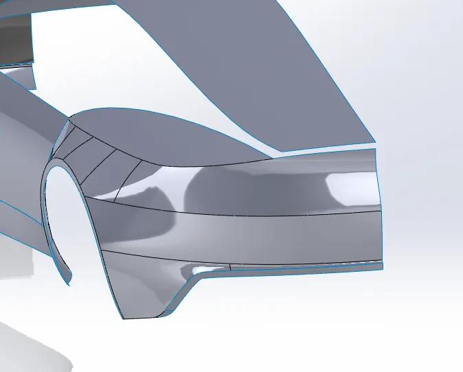
The rear of the car consists of The hood,The rear bumper etc.The features used for the rear of the car are as follows:
- Projected curve
- Extrude surface
- Surface trim
- Filled surface
- Boundary surface
- Rules surface
- Sweep surface
- Loft surface
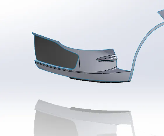
Front Bumper
The front bumper is the part below the grille of the car.The features used for the car are as follows:
- Projected curve
- Extrude surface
- Surface trim
- Filled surface
- Boundary surface
- Rules surface
- Sweep surface
- Loft surface
Hood,Windows,Doors
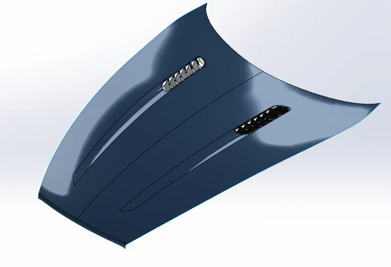
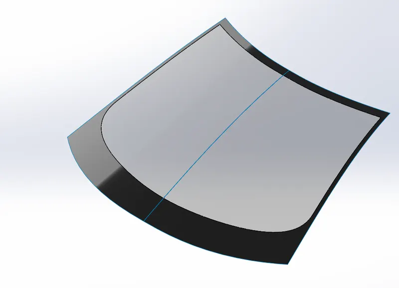
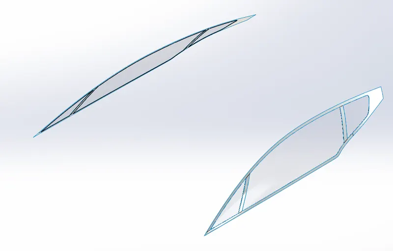
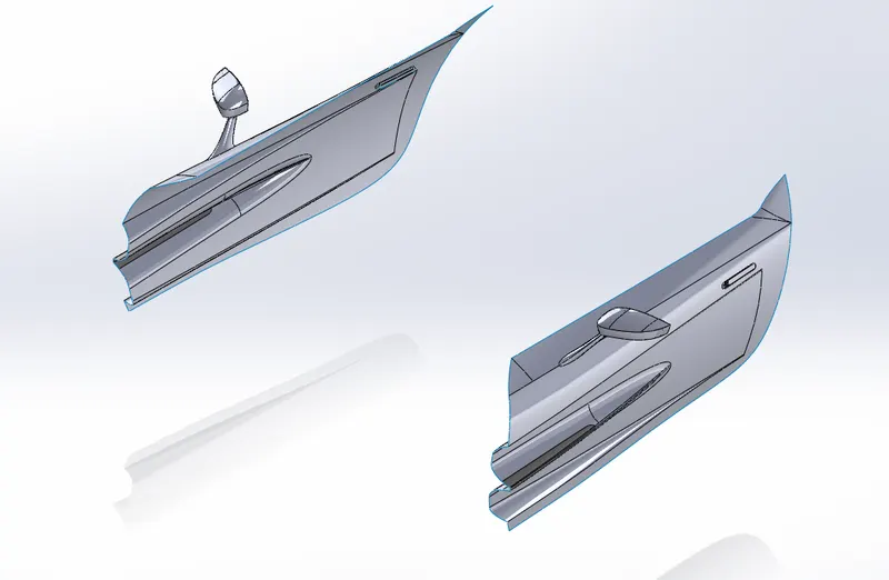
The Hood covers the engine part of the car.The windows consists of the front Windshield,The side windows,The rear windows.All of which are cut from the car body and exported into new parts.The main features used are as follows.
- Split
- Split line
- Trim surface
- Insert into new part
- Projected curve
- Extrude surface
- Surface trim
- Filled surface
- Boundary surface
- Rules surface
- Sweep surface
- Loft surface
- Move/Copy bodies
- Linear pattern
- Extrude Boss/Base
- Intersect feature
- Thicken
- Extrude cut
Hood
Windshield
Rear Window
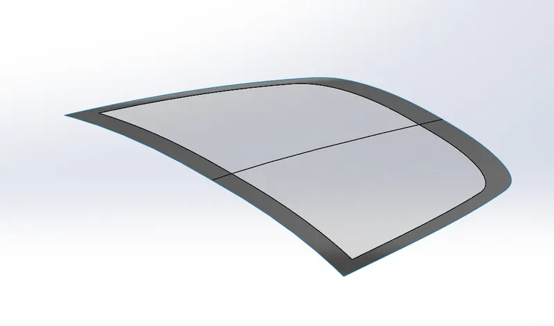
Side Window
Doors
Front Wing
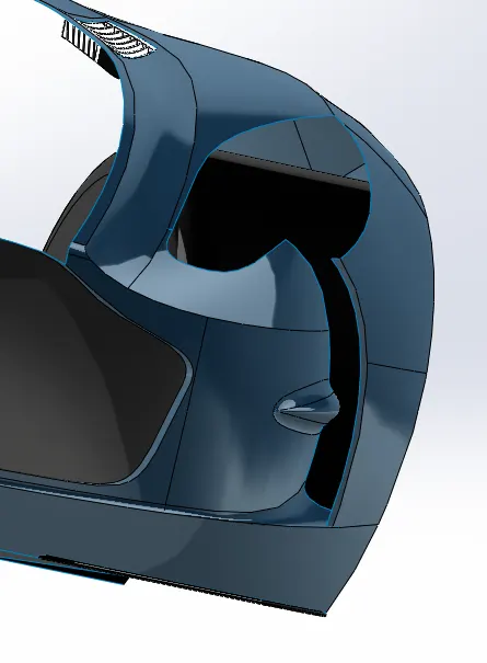
The front wing is the part of the car through which air can pass into the car.The features used are:
- Projected curve
- 3D sketch
- Extrude surface
- Surface trim
- Filled surface
- Boundary surface
- Rules surface
- Sweep surface
- Loft surface
Grille
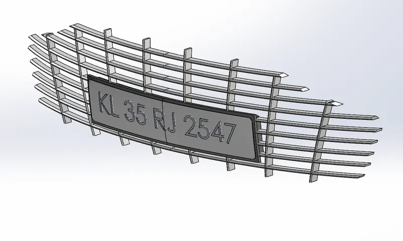
The grille is an iconic part of the Aston Martin cars.The design of the grille is so beautiful.This grille allows flow of air into the engine compartment where the coolig equipments and the air intake is situated.The features used are:
- Spline
- Extrude Boss/Base
- Split
- Combine
- Mirror
- Fillet
- Text
- Offset surface
- Cut with surface
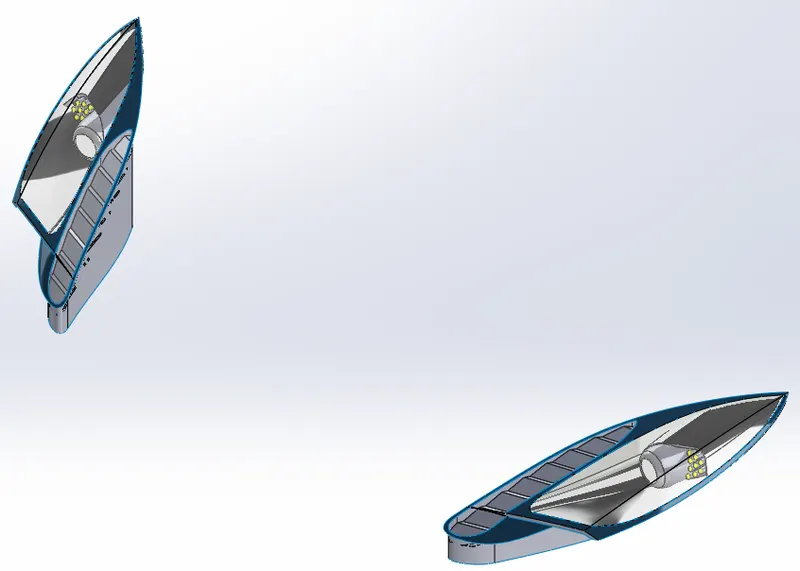
Lights
The lights consists of the projected lamps,The daytime running lamp the indicators etc.The features used are as follows:
- Split tool
- Insert into new part
- boundary surface
- variable radius fillet
- Move/Copy bodies
- Thicken
- cut with surface
- Revolve
- Split line
- Extrude Boss/Base
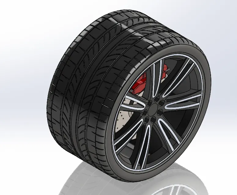
Wheels and Brakes Assembly
The wheels and brake assembly consists of the Tyres,The Rims, The brake disc,The brake calipers.The features used are as follows:
- Revolve
- Extrude
- Chamfer
- Mirror
- Cut with surface
- Cut extrude
- Split line
- projected curve
- sweep Boss/Base
- Move/Copy base
- Fillets
- Appearence
- Mates
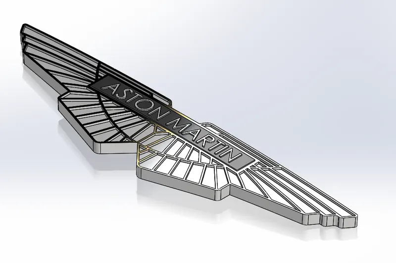
⦁ Aston Martin Emblem
The emblem of Aston MArtin consists of :
- Extrude Boss/Base
- Extrude cut
- Mirror
- Fillets
- Appearence
Full knitted model of the car
Assembly of the whole model
The models created are assembled in the assembly workbench.Assembly is done by using Mates such as:
- Coincident mate
- Distance mates
- Width mates
- Angle mates
Front View
Back View
Side View
Isometric View
Photorealistic rendering
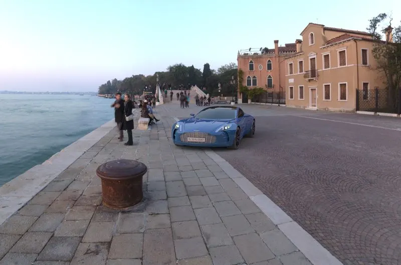
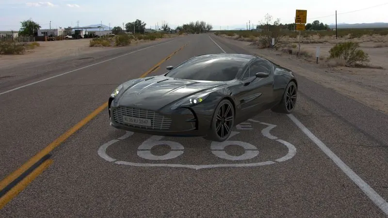
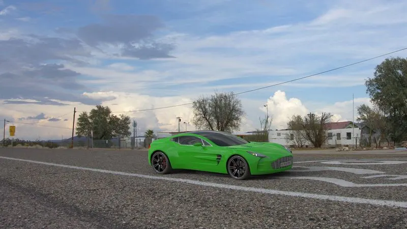
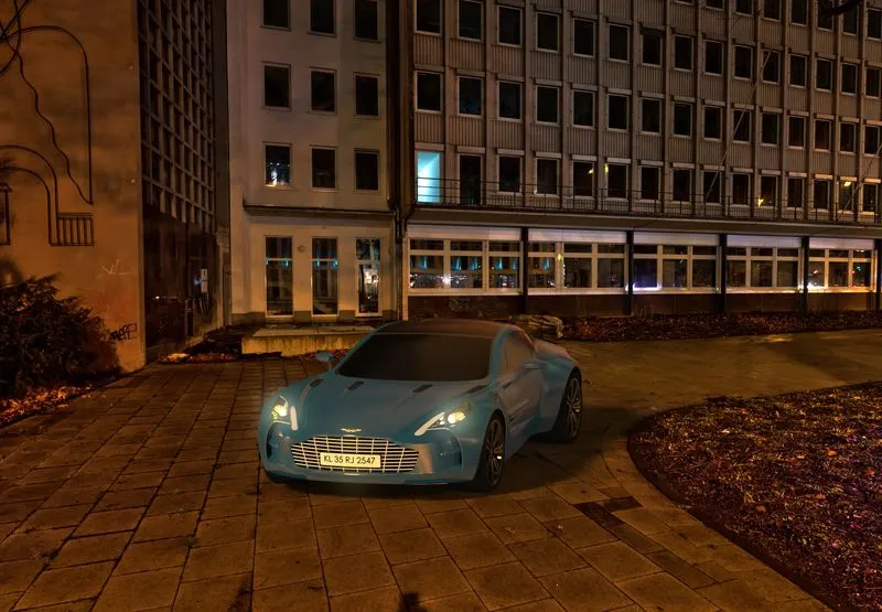
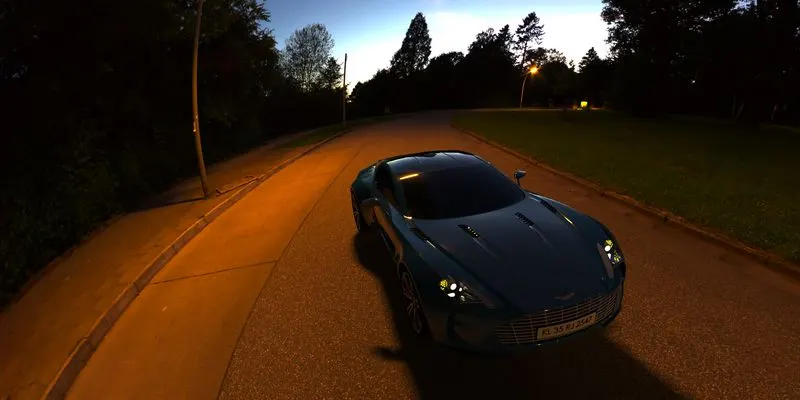
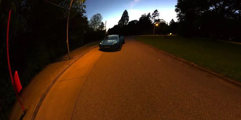
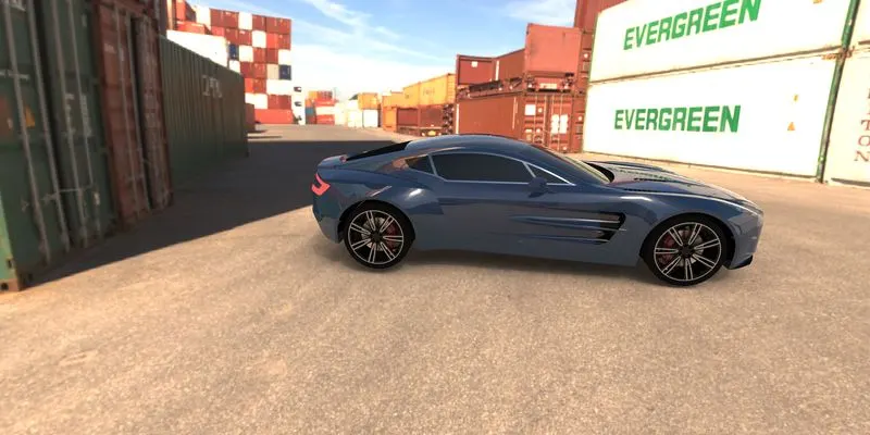
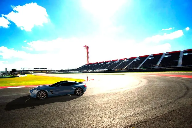
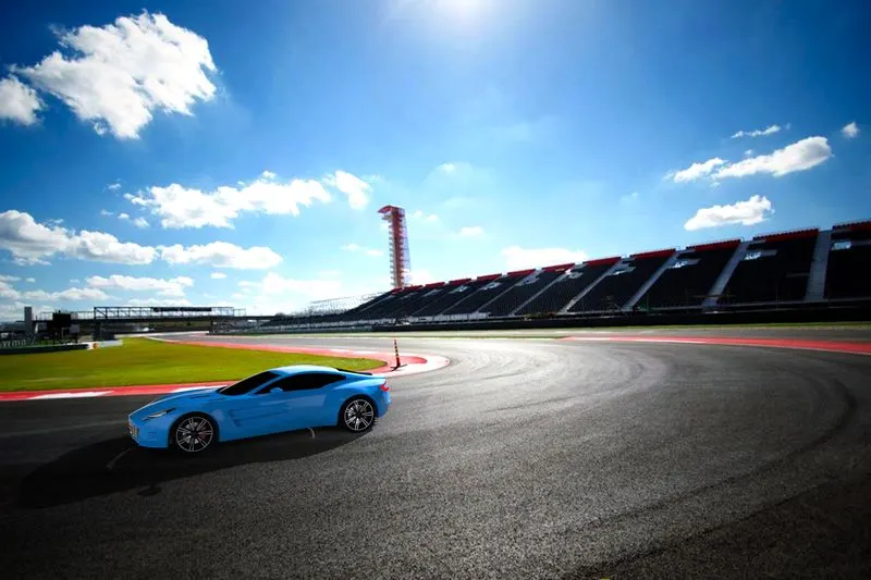
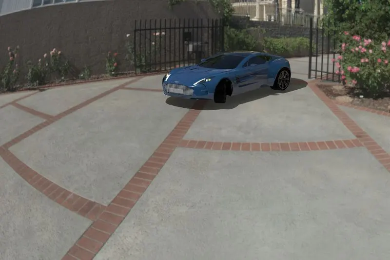
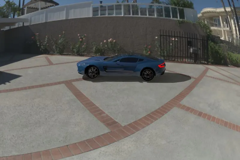
The full assembly is Rendered using the Solidworks visualizer giving proper lighting and background.Solidworks visualize is a standalone Render engine for Solidworks.This works independent of Solidworks so there wont be any licence issues when doing the rendering.In visualize also we can change the Environment.Plates can be added as background images.Camera views can be changed.Views can be changed from perspective to orthographic.The rendered images are provided below.
Conclusion
The project gives the opportunity to learn about Solidworks and the features in solidworks part modelling such as solid modelling and surface modelling.Also the assembly of the Aston Martin One-77 gives a deep understanding about the different assembly mates.The Solidworks visualizer is very good in giving realistic images of parts modelled and gives the opportunity to play with out creativity.