Wiring harness routing & packaging Rules Week 3 Challenge
Q1. Download the following cad data & define it as Electrical support using the Electrical Part Design Workbench. Define all the necessary properties.
A FLOW CHART IS DRAWN AND SHOWS BELOW WHAT ALL METHODS ARE GOING TO USE IN THE MODEL.
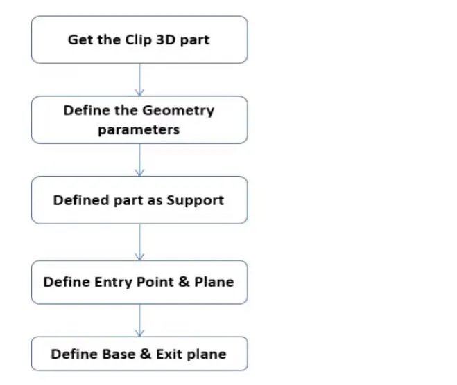
- The given clip was downloaded and opened in CATIA as a part file.
- And define two points that will be used as entry and exit points.
- after that, a plane has to be created at the points.
- A base plane has to be defined at a distance of 2 to 3 mm from the clip.
- again we define the exit point in the first definition as the entry point.
- finally, we got two entry and two exit points.
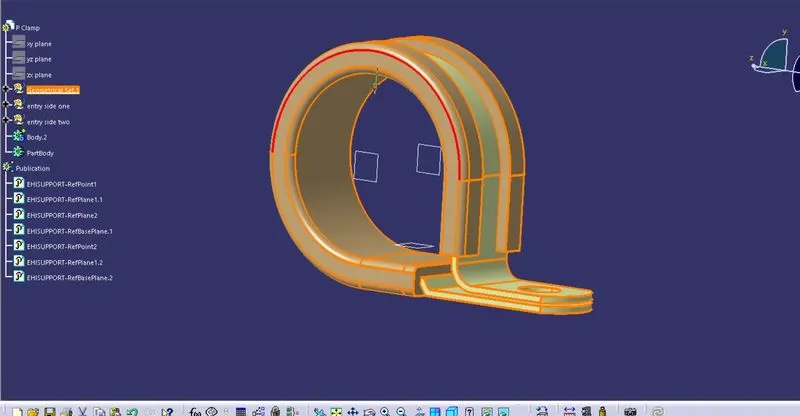
TREE STRUCTURE IS SHOWN FOR THE P-CLAMP
Download following Back shell cad data & define it as Electrical back shell using Electrical Part design Workbench. Define all the necessary properties.
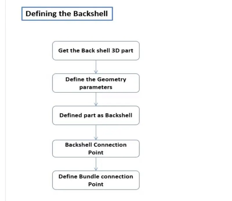
- The backshell data was downloaded from the website.
- We define the points in the part workbench.
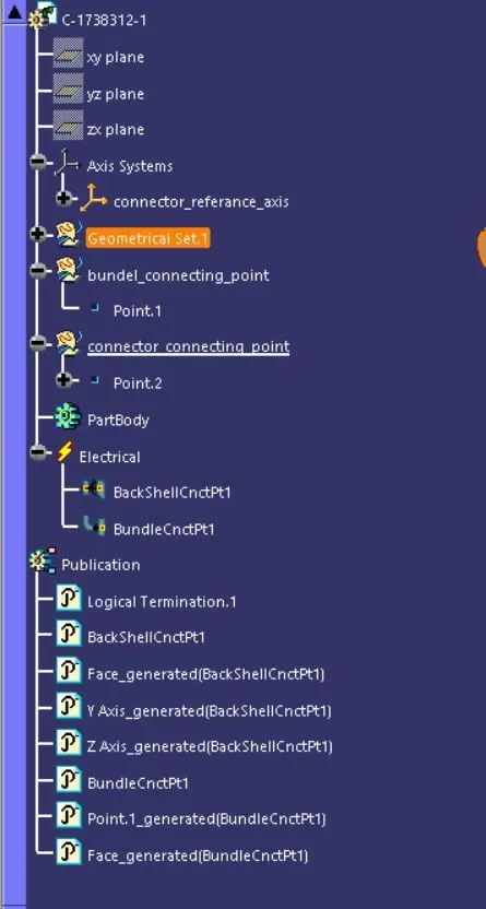
- An Axis system with the correct axis orientation is placed at the backshell connection point.
- The points have to be defined as the backshell connection and bundle connection points.
DEFINING AS BACK SHELL
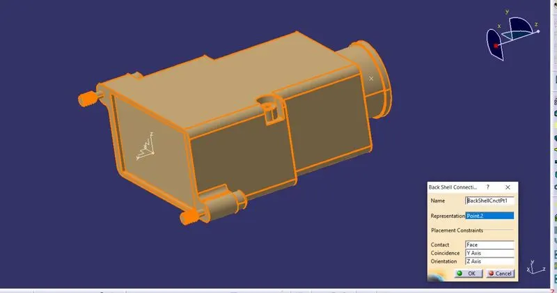
AXIS SYSTEM IS CREATED ON CONNECTOR CONNECTING POINT
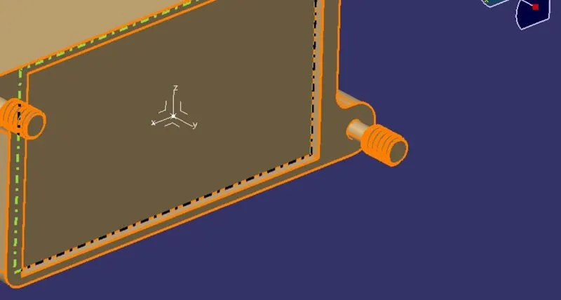
REFERENCE IMAGE IS SHOWN BELOW
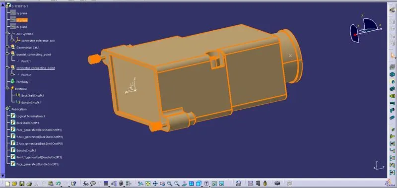
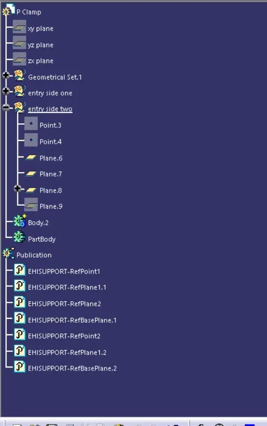
TREE STRUCTURE IS SHOWN FOR THE P-CLAMP
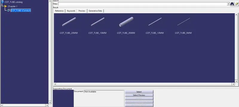
Q3. Create Following Corrugated tubes & Add them in Catalogue under “Slit COT” family.