Wiring harness routing & packaging Rules Week 3 Challenge
Wiring harness routing & packaging Rules
Q1. Download following cad data & define it as Electrical support using Electrical Part design Workbench. Define all the necessary properties.
Wire Harness Assembly Structure- Clip Definition
CLIP DEFINITION-
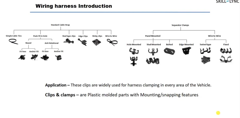
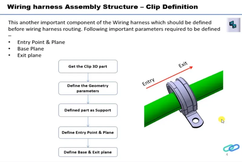
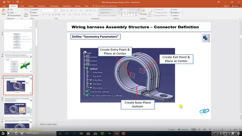
Process:
- Create two points one as entry and another as exit point.
- create planes at two points and another at base.
- Switch to Electric part desgn
- Click on support defination - select part - select entry point - select entry plane, exit and base plane.
- Again Click on support defination - select part - select exit point - select exit plane and base plane as secondary plane is automatically take.
1) Point Creation:-
Point - 1
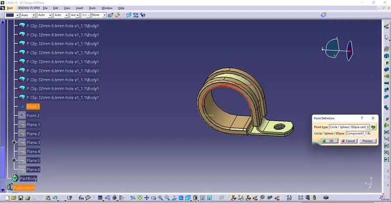
Point - 2
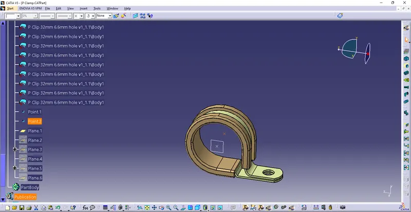
Plane - 1
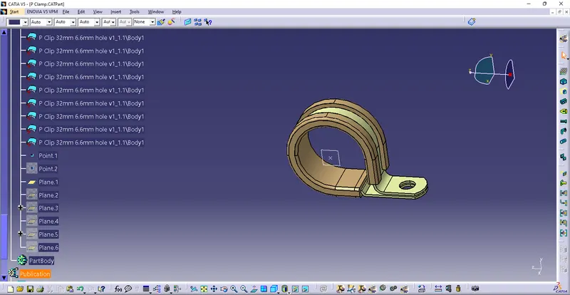
Plane - 2
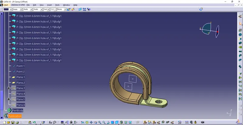
Base Plane -
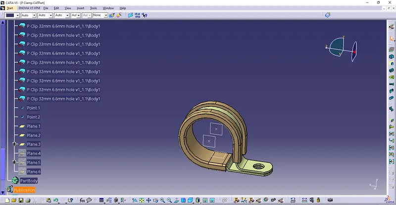
Define as Support -
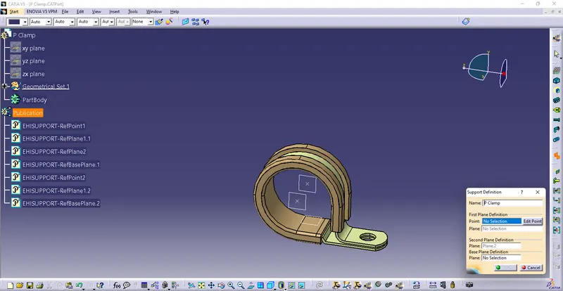
Q2. Download following Back shell cad data & define it as Electrical back shell using Electrical Part design Workbench. Define all the necessary properties.
Tyco 1738312-1 https://www.te.com/usa-en/product-1738312-1.html
Wire Harness Assembly Structure- Backshell Definition
Backshell Definition
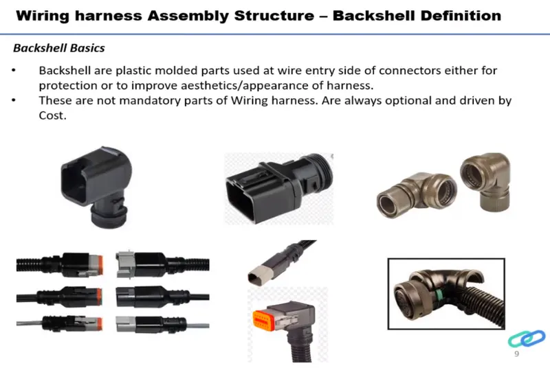
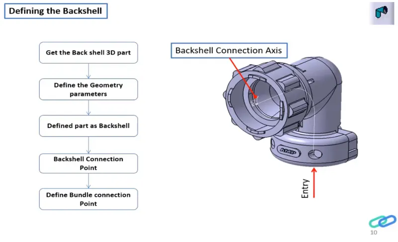
Process-
- Once the File is Downloaded, Open the File Using CATIA V5
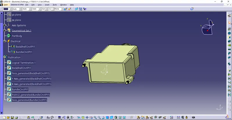
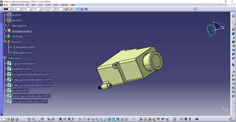
- Using the Part design model, we define 2 points as the Bundle entry and Connector connection point with Axis
- After determining the points and planes open the file in Electrical Part design
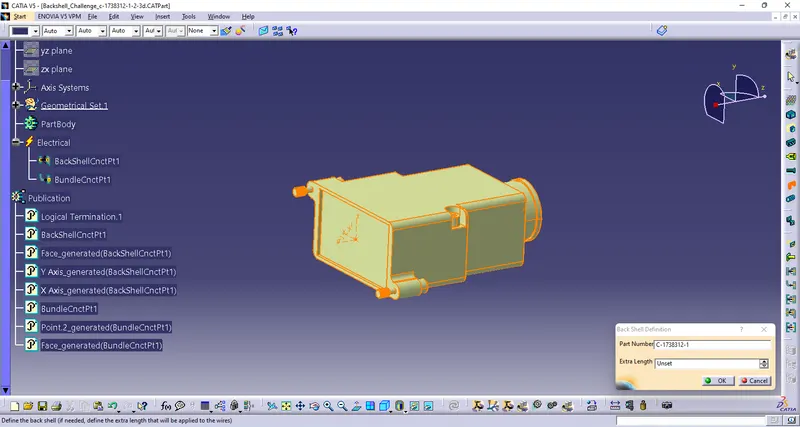
- Now we need to define the part as a Backshell using Define Back shell Feature
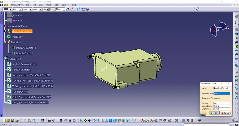
- After defining it as the Backshell we need to define the connection points
- End, where the Back shell is connected with the connector, is defined using Define Back Shell Connection Point Feature
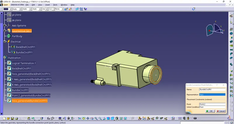
- End where the bundle is connected to the back shell defined using Define Bundle Connection Point Feature
- After giving the necessary properties Save the file.
1) Create Points and Axis-
2) Define as Backshell -
3)Backshell connection Point-
4) Define Bundle Connection Point-
Q3. Create Following Corrugated tubes & Add them in Catalogue under “Slit COT” family.
|
Name |
ID (mm) |
OD (mm) |
Thickness (mm) |
|
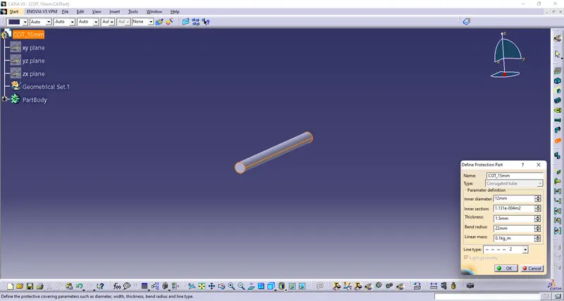
15mm COT |
12 |
15 |
1.5 |
|
20mm COT |
17 |
20 |
1.5 |
|
35mm COT |
32 |
35 |
1.5 |
|
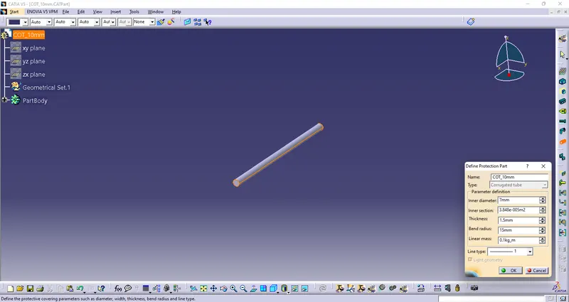
10mm COT |
7 |
10 |
1.5 |
|
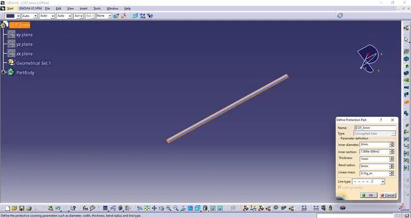
5mm COT |
3 |
5 |
1 |
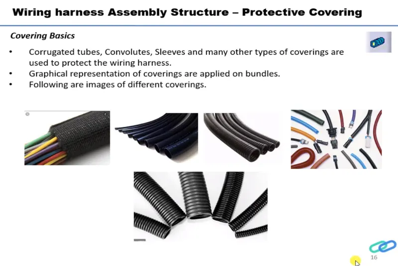
Corrugated tubes-
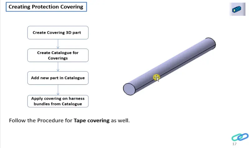
Process-
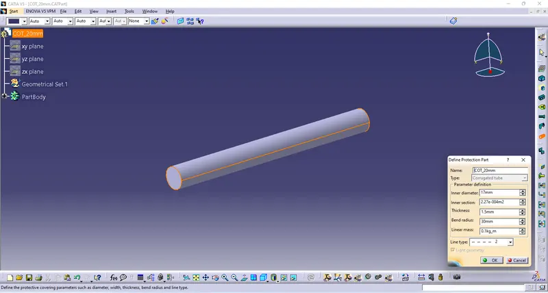
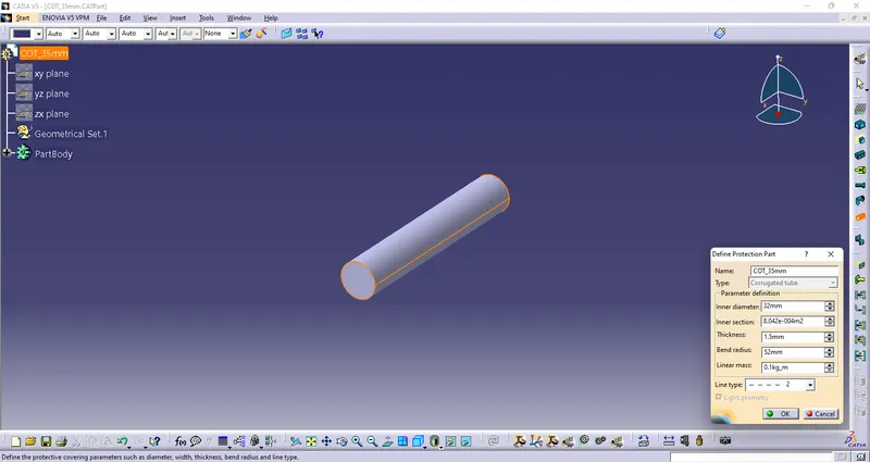
- we define the cot tubes in the electrical part workbench.
- the inner dia & thickness are given as the inputs.
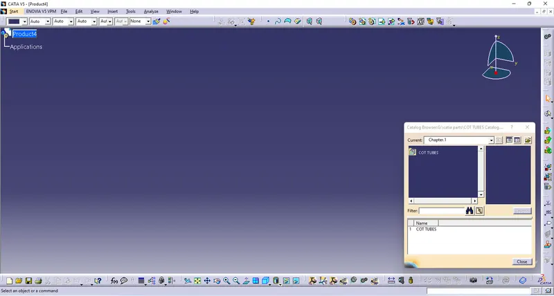
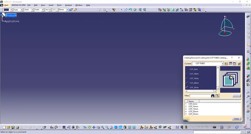
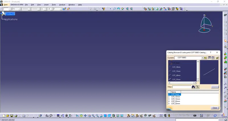
- a catalog was created for the cot tubes.
- all the cot tubes were saved in the catalog.
1) 5mm COT-
2) 10mm COT-
3) 15mm COT-
4) 20mm COT-
5) 35mm COT-
Create Catalog-