Wiring harness routing & packaging Rules Week 3 Challenge
REPORT WRITING FOR P-CLAMP :-
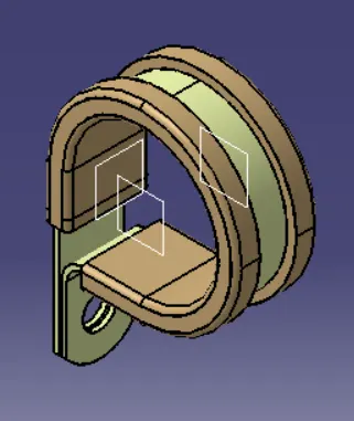
According to the given question at first we need to download the CAD files of P-Clamp then using Electrical Part Design workbench we will define it as a Electrical support for that we need to do certain Steps such as:-
- First we need to do Geometry Parameters such as Entry POINT & PLANE, Base Plane and The Exit plane in Part design workbench.So, First we need a POINT in Entry plane so Click to POINT toolbar , in the POINT type select the circle/sphere option then select the part and press Ok POINT 1 Created . Then Rotate the Model and again Click POINT toolbar same type and Press Ok POINT 2 Created , Now we Have Entry and Exit POINT .
- Then to Create a Entry Plane , Exit Plane and Base Plane , Select the PLANE Toolbar in the Entry side select the plane type "Parallel through point" , reference is the face of the entry side, and select POINT 1 which we have created ,then press OK,Plane -1 Is created ,then for Exit Plane Rotate the Model Press PLANE toolbar same type in reference select exit face and in POINT select the POINT-2 and press OK Plane -2 is created, Now for the base plane again select PLANE toolbar then type Will be "OFFSET from PLANE" , then in reference select a face for the plane then Give 2mm Offset ,Plane-3 is created . Save the model .
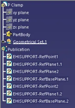
- Then to define as a Electrical support switch to Electrical Part Design Work Bench , Then Click "DEFINE SUPPORT PART" in the toolbar then click to the body , now you can see a dialogue box let the name be same as P CLAMP , so in First plane Defination or the entry plane select The Point -1 and Plane -1 , then in the second plane Defination or exit plane select plane -2 and for Base plane defination select Plane-3 , Click OK . Now you can see in the feature tree the properties are added in Publications and part body .
- NOTE- In (P-Clamp there are 2 Entries and 2 Exits available) , so we need to define the entry and exit from the other side also .
- So again select " DEFINE SUPPORT PART " click the body then a dialogue box apper let the name be same , this time in the Entry plane select POINT- 2 and Plane -2 , then in the exit plane the selection will Plane -2 by default because earlier we have selected it , then select the base plane -3 , then Press Ok .
- Now the Clamp is defined as Electrical support part and ready to use in the wiring harness bundle.
REPORT WRITING FOR BACKSHELL TYCO-1738312-1 :-
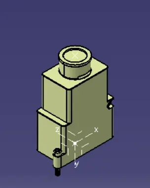
According to the given question at first we need to download the CAD files in .IGS format from Tyco Electronic website as given , then to define TYCO 1738312-1 as Electrical Backshell using Electrical Part Design workbench , we need to do certain Steps such as:-
- First we need to do Geometry parameters such as PONTS & AXIS , So first we need a POINT in the Backshell connecting connection point so take POINT toolbar , select 2 Points ,press MiddlePoint and press OK ,we got POINT-1 , go to AXIS toolbar select origin as POINT-1 , Keep the X,Y,Z axis according to orientation and mounting the backshell to the Connector .
- Also we need a POINT in the Bundle Entry side , So Click to the POINT toolbar then Point type select Circle/sphere then click to edge ,then press OK . POINT -2 is created , Save the Model .
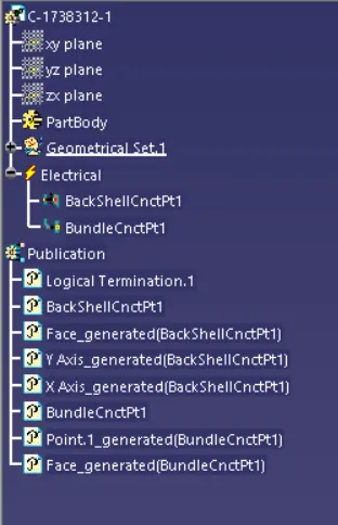
- Then Switch to Electrical Part design Workbench, then Select "DEFINE BACKSHELL" from the toolbar ,then click to the body a dialogue box appears then let the part number accordingly and in Extra length let it be UNSET .then Press OK .
- Then we have to define the backshell connection point so, Select "DEFINE BACK SHELL CONNECTION POINT" in the toolbar , select the body a dialogue box appear , then let the name be as it is , in the representation select the POINT-1 which we have created , in the contact select the face which is going to mate with the connector , Coincidence Y-AXIS , Orientation X- AXIS . Press OK . save the model .
- Then we have to define Bundle connection point so, Select "BUNDLE CONNECTION POINT" in the toolbar then select the body , let the name be as it is , in representation select the face , in Point select the POINT-2 which we created and in Initialcondition is same face which is normal to the bundle entry .Then Press OK . Save the part .
- Now the Backshell TYCO-1738312-1 is defined as Electrical back shell and ready to use in the wiring harness bundle.
REPORT WRITING FOR CORRUGATED TUBES(COT):-
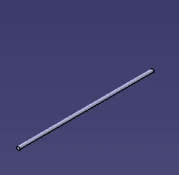
According to the given question the Corrugated tubes cannot be downloaded , we have to create the tubes through "DEFINE PROTECTION PART '' toolbar in Electrical part Design workbench , Steps are :-
- First we need to Create a new part file , open the electrical work bench then click to the "DEFINE PROTECTION PART'' then we have to click the part a dialogue box appear .
- Then Give the Internal Diameter , thickness according to the requirement or provided by the manufacturer , here in this case according to the question.
- Then the bend radius we have to calculate it by 1.5x times of the given outer diameter . Then press OK
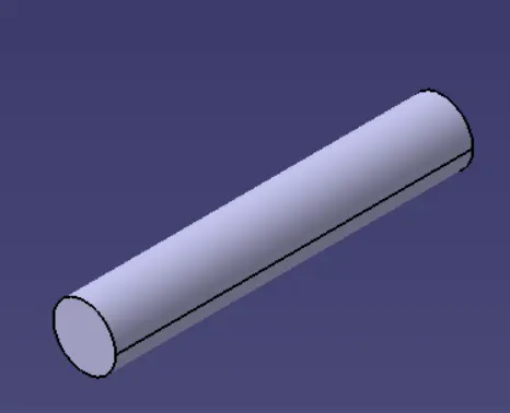
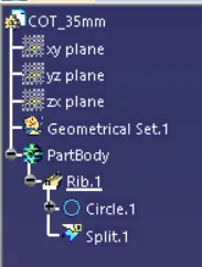
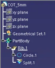
- You can see we have created a COT Tube as asked in the given question according to sizes we have to create .
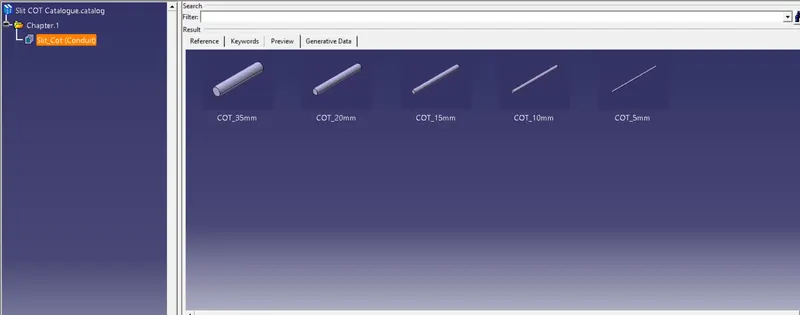
- Then Open a new file as catalogue document , then add family then save it naming SLIT COT , then store all the COT tubes we made .
- So the COT tubes we made are defined and we can use it for wiring harness