Wiring harness design in CATIA V5 - 3D modeling Week 4 Challenge
REPORT WRITING FOR WIRING HARNESS ASSEMBLY:-
According to the Question ,first we need to download all the given Connectors given through Tyco Electronics Website ,then we need to follow certains Steps:-
- After downloading we have to define all the connectors Electrically .
- Then for the layout we need to create a reference sketch according to given structure in the question.
- Then Create a new Product file , add the Reference sketch , then add the Connectors .
- Align all the Connectors using the "Snap" command in "Assembly Design" Workbench ,"Manipulation" Command in "Assembly Design" Workbench and Compass Tool and Connect all the Connectors Connection Point to Reference Sketch Points according to the given diagram in the Question.
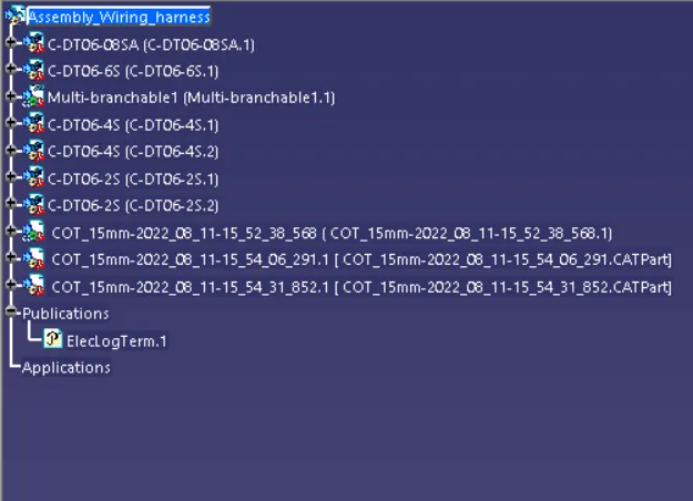
- Then Open The "Electrical Harness Assembly" Workbench , Click To Geometrical Bundle Command and select the Assembly wiring harness Product and in the Feature tree You can the your Product is Defined .
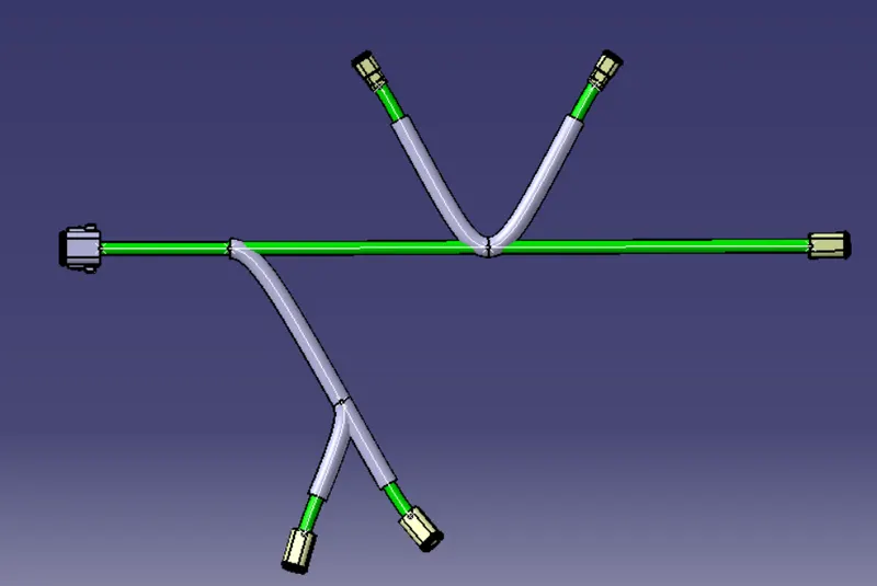
- Then Select "multi-Branchable Document" Command ,then a dialgue box appears ,let the name be as it , set the required diameters here i have provided 10mm ,Bend radius Ratio will always be 1.4 or 1.5 times greater than the diameter . In the Build Mode let the Mode be slack , provide Slack % according to industry requirement , in my case its 0 . then Click "Route Defination" and select DT06-08SA and check direction is towards connector DT06-6S and also select the connector DT06-6S . Check the Reverse tangent and press OK , Now you can see The Main Branch Bundle is created
- Now For the Sub branches we have to create Branch Point . So select the " Branch Point" Command and dialogue appears, now select the branch , then in lenght give the required data , now in my case i want to create the sub branch in the below side of the sketch so provide the length as 150mm . You can see Branch POINT-1 is created .
- Then Click to The "Branch Defination" Command then select the Branch Point -1 created then select the DT06-4S connector and check the direction and Reverse tangent , and Sub branch is created . So , Again we have to created a Branch Point for the other Connector DT06-4S and have to follow the same steps.
- Now for the Above 2 same Connectors DT06-2S we have follow the same steps , first to Create the branch Point then giving branch defination selecting the point and connectors , and also checking the Directions and Reverse Tangent .
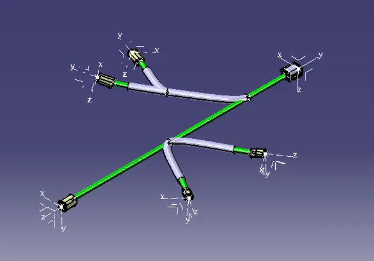
- Now according to Question we have to give Protecting covering to the Upper and Lower Sub Branches . So, Select "Protective Covering" Command select the Upper Branch and in the End extremity we have Keep 30mm apart and same for the lower branch also . Save The data
- Below i have inserted some images of my Wiring Harness Assemble Routing Model .