Wiring harness design in CATIA V5 - 3D modeling Week 5 & 6 Challenge
REPORT WRITING FOR HARNESS ASSEMBLY A+B ROUTING :-
- After Downloading all the CAD data provided we need to define them electrically with POINTS & AXIS Geometry and then define their Bundle Entry Point and Connector Connecton Point by the created the Geometry .
- Then Open a New part Draw a Reference sketch according to the HARNESS A&B mapping Data provided.
- Then Create a New Product-1 for Harness A assemebly and Align the Connectors according to the Mapping Data Through Snap Tool Or using the Compass tool . same process For Harness B assembly
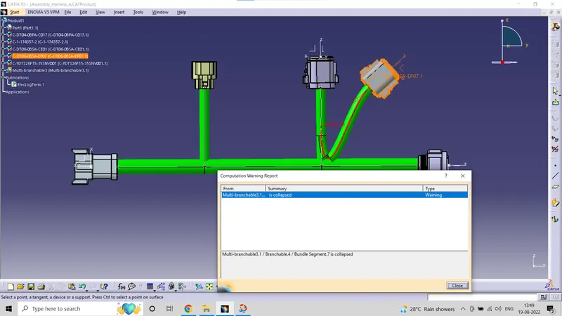
- Then Define the Product 1 and Product 2 by Geometric Bundle .
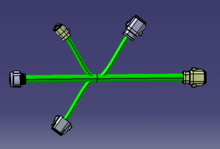
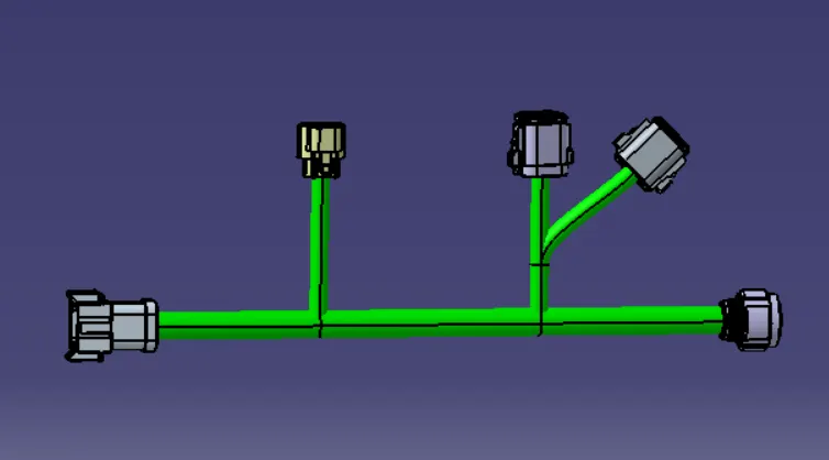
- Then Rout the Connectors according to alignment , Creating Main Branches and Sub Branches . Then Check the Bundle Continuity for any error .Do this Process For Both Harness A and B assembly Products .
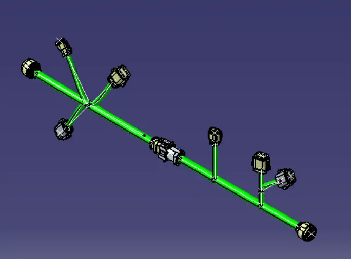
- Then Open a New Product and name it as Final Assembly A+B then, open both the product in the newly created Product then go to ''Electric Assembly Design'' Workbench then Interconnect the Connector-5 & 6 using "Connect electric Device" tool . ( Note- Keep the AXIS Geometry same For Both the Connectors to mate)
- Now add the Annotations for the connectors accordingly .
- Save The File in (.igs) format , Now you can Use this harness assembly bundle .