Project 1
REPORT WRITING FOR PROJECT-1
According to the given assignment, first we need to download all the CAD data provided, then for the Engine context assembly, Flattening and drawing we have to follow certain Steps to follow such as :-
- We have to Define all different types of Connectors, Clips, Clamps, Protecting Coverings (Channel) Electrically by using certain Geometry Parameters.
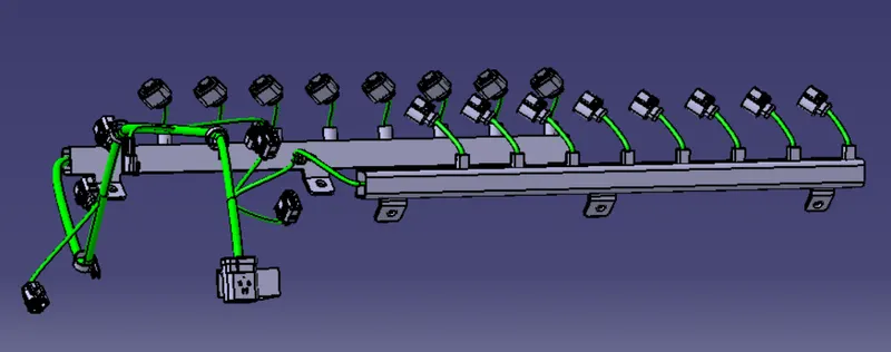
- Then We have create a new Product file and add the Engine Component , then add new product assembly file in the main product file then we have start Positioning the connectors to the engine so that we can provide Electrical properties to the Engine.
- First we have to position the Interconnection Connector using the L-Clamp, then injector Connectors, then for different types of Sensors in the Engine .
- Then We have to add some Electrically defined Clips, Clamps and Protecting Coverings Such as Channels.
- After Adding all the connectors , Clips and Clamps , we have to start Routing .
- First We have to Start routing From the Interconnection Connector and create a Main Branch ,then Sub Branch Points to create sub branches for connecting rest connectors.
- After Routing all the Connectors with support of Clips and Clamps, We can proceed for flattening.
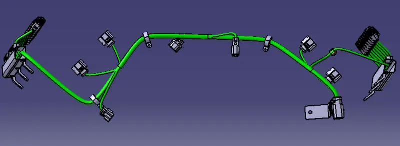
- So create a new Product file ,go to the flattening workbench then set Flatenning parameters, then extract the Geometrical set Product from the Engine assembly product .
- Then Click to Flatten toolbar , Then Select a Active plane in the model and select the main branch then select all the branches, Then using various tools such as Rotate , Junction Command etc , arrange the Model, All the connector should be oriented in the locking side .
- After the Flattening we have to create a new drawing file ,then select the Front view in the toolbar and select the Active plane which selected while flattening the model .
- So , Now We have created the Engine Assembly Product , Engine Flattening Product and the engine assembly drawing .