Wiring harness design in CATIA V5 - 3D modeling Week 2 Challenge
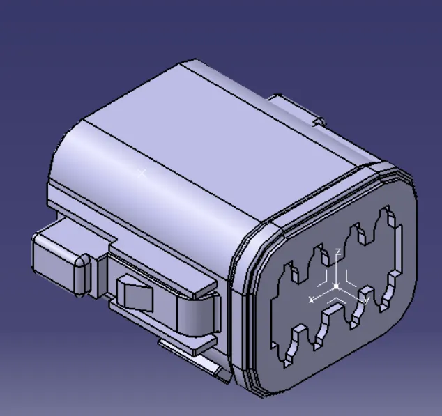
REPORT WRITING FOR CONNECTOR-DEUTSCH (DT)06-08SA :-
According to the given question at first we need to download the CAD files in .STP format from Tyco Electronic website as given , then to define DT06-08SA as Electrical connector using Electrical Part Design workbench , we need to do certain Steps such as:-
- First we need to do Geometry parameters such as POINTS & AXIS to the Bundle entry point and Connector connection point. So first, POINT Parameter is given to the Bundle entry point through which the middle point-1 is generated ,then POINT Parameter is given to the Connector Connection Point , through which Middle point-2 is generated then The AXIS parameter is given to the connector connection point by selecting the point-2 in the origin and giving X,Y,Z axises cooridinates accoring to the locking Mechanism of the connector .
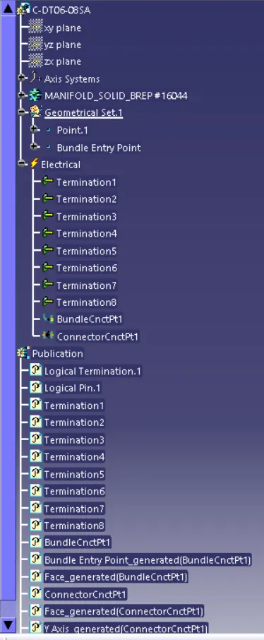
- Then open the Workbench select Electrical part design, then click to the command "Define Connector" in the tools section, then select the connector Geometry then a dialogue box will appear, select " Single insert connector" as a type , keep the same part number then determine the number of termination by looking to the connector and in this case as you can see DT06-08SA has 8 pole , So the termination will be 8Nos. After that you can see in the feature tree the connector is electrically defined .
- Then we need to define Bundle Connection point by selecting the command in the right hand side of the toolbar then click to the connector body again , then a dialogue box will appear , let the name be as it is , in representation select the entry face of the connector , then select the (point-1) which we have created at Bundle entry point , Then initial condition will always be the same or Perpendicular to the face of the representation . Then Press OK , Now you can see in the feature tree the Bundle Entry connection point is defined and added in the properties, Then save The Data .
- Now we need to Define Connector Connection Point , for that click to the connector connection point command in the right hand side of the toolbar, then a diaogue box will appear , then again let the name be same in the representation select the connector connection (point-2) which we have done earlier in the geometry parameter, then the contact will be the face of the connector Mating face, the coincidence face will be the Y-Axis & the orientation will be X-Axis ,Now you can see in the Feature tree there are 2 Things added ,one is the connector connection thing in the Electrical Properties & the second is the Reference Used for this Properties. Now Save The Data .
- The next step is the Cavity Connection point but in the connector DT06-08SA as we don't have the locking Feature so this Connector is now Completely Defined and we can use it further for Wiring harness Drawing creation .
REPORT WRITING FOR CONNECTOR- TYCO 174357-2 :-
According to the given question at first we need to download the CAD files in .STP format from Tyco Electronic website as given , then to define TYCO 174357-2 as Electrical connector using Electrical Part Design workbench , we need to do certain Steps such as:-
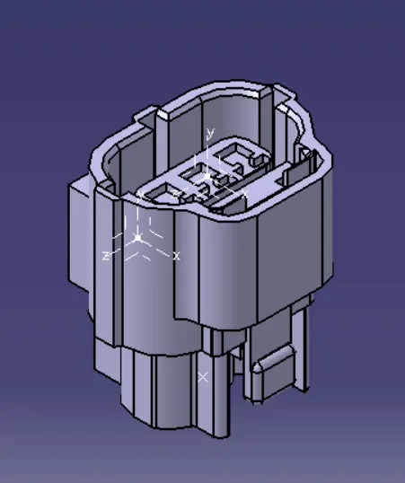
- First we need to do Geometry parameters such as POINTS & AXIS to the Bundle entry point and Connector connection point. So first, POINT Parameter is given to the Bundle entry point through which the middle point-1 is generated ,then POINT Parameter is given to the Connector Connection Point , through which Middle point-2 is generated then The AXIS parameter is given to the connector connection point by selecting the point-2 in the origin and giving X,Y,Z axises cooridinates according to the locking Mechanism of the connector . Here ,we need to give another set of Geometry parameters of POINTS & AXIS for the Cavity Connection point , where the Mounting of cavity clip in the connector clip will take place , So Point-3 is generated through the middle point feature and the AXIS is created through selecting point-3 as origin and the X,Y,Z axises will be coordinated along the Mounting of the cavity Clip . Save the Model. (NOTE- Same Orientation Should be provided in the Connector clip and the Mounting Clip ).
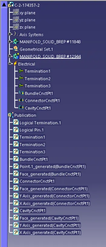
- Then open the Workbench select Electrical part design, then click to the command "Define Connector" in the tools section, then select the connector Geometry then a dialogue box will appear, select " Single insert connector" as a type , keep the same part number then determine the number of termination by looking to the connector and in this case as you can see TYCO 174357-2 has 3 pole , So the termination will be 3 Nos. After that you can see in the feature tree the connector is electrically defined .
- Then we need to define Bundle Connection point by selecting the command in the right hand side of the toolbar then click to the connector body again , then a dialogue box will appear , let the name be as it is , in representation select the entry face of the connector , then select the (point-1) which we have created at Bundle entry point , Then initial condition will always be the same or Perpendicular to the face of the representation . Then Press OK , Now you can see in the feature tree the Bundle Entry connection point is defined and added in the properties, Then save The Data .
- Now we need to Define Connector Connection Point , for that click to the connector connection point command in the right hand side of the toolbar, then a diaogue box will appear , then again let the name be same in the representation select the connector connection (point-2) which we have done earlier in the geometry parameter, then the contact will be the face of the connector Mating face, the coincidence face will be the Y-Axis & the orientation will be X-Axis, now Save the Data .
- The Next Step is to define Cavity Connection Point , Click to Cavity Connection Point command in the right hand side of the toolbar ,then click to the connector body a dialogue box will appear ,let the name be the same , in the representation select the point-3 which we have created , in contact select the face of the connecting clip , in Coincidence select the Y- Axis, and in the Orientation select the X -Axis. now u can see in the Feature tree the cavity connection part is added in the Electrical properties and also te references added . Save The Data .
- So this Connector is now Electrically Defined and we can use it further for Wiring harness Drawing creation .
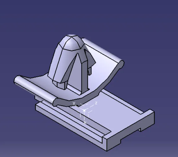
REPORT WRITING FOR CONNECTOR CLIP-TYCO 85229-1:-
According to the given question at first we need to download the CAD files in .STP format from Tyco Electronic website as given , then to define TYCO 85229-1 as Electrical connector clip using Electrical Part Design workbench , we need to do certain Steps such as:-
- First we need to do Geometry Parameters Such as POINTS AND AXIS at Mounting face of the clip , So click to POINT toolbar then a dialogue box appear where the point type will be on curve ,then select middle point and Point-1 is created in the mounting face of clip. Now for AXIS parameters select the toolbar ,then in the origin select the Point-1 and set the X,Y,Z axis orientation according to the insertation of connector clip and the connector. Save the Part.
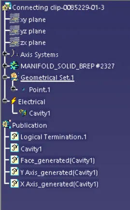
- Now to define the mounting clip , go to the "Electrical Part design" Workbench , then click to the command "Define Mounting Equipment" ,click to connector click and press OK.
- Now Click "Define Cavity" in the toolbar and press connector clip part , then a dialogue box appear , in representation select the point -1 which we have created , in contact we have to select the face that is going to mount , in coincidence we have to select the Y-AXIS and in orientation we have to select X-AXIS .Save the Data.(NOTE- Same Orientation Should be provided in the Connector clip and the Mounting Clip ).
- So this Connecting Clip is now Electrically Defined and we can use it for Assembly with the connector using Electrical Assembly Design Workbench .