Wiring harness routing & packaging Rules Week 3 Challenge
OBJECTIVE:
- Define Electrical support using the Electrical Part design Workbench. Define all the necessary properties.
- Define Electrical back shell using Electrical Part design Workbench. Define all the necessary properties.
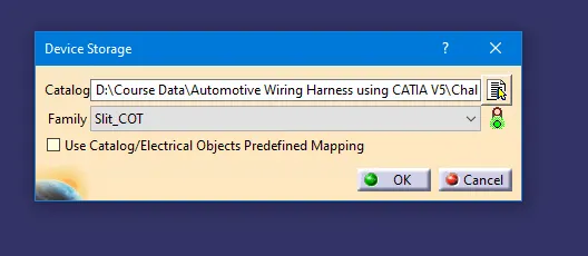
- Create Corrugated tubes & Add them to the Catalogue under the “Slit COT” family.
INTRODUCTION:
Electrical support is an electrical component that is used to clamp and hold the electrical wire bundle to the vehicle body. There is a wide variety of clamps called P clamp, Sticky clamp, furr tree, stud type, hole mounted type clamps.
Backshells are plastic molded parts used at the wire entry side of connectors either for protection or to improve the aesthetics/appearance of the harness. These are not mandatory parts of the Wiring harness. Are always optional and driven by Cost.
Corrugated tubes, Convolutes, Sleeves, and many other types of coverings are used to protect the wiring harness. Graphical representations of coverings are applied on bundles.
ELECTRICAL SUPPORT DEFINITION:
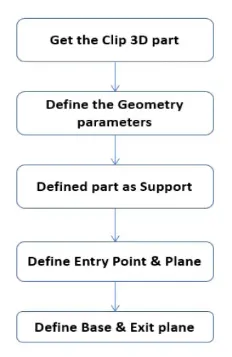
The following parameters are required to define Electrical Support:
- Entry Point & Plane
- Exit Point & Plane
- Base Plane
PROCESS:
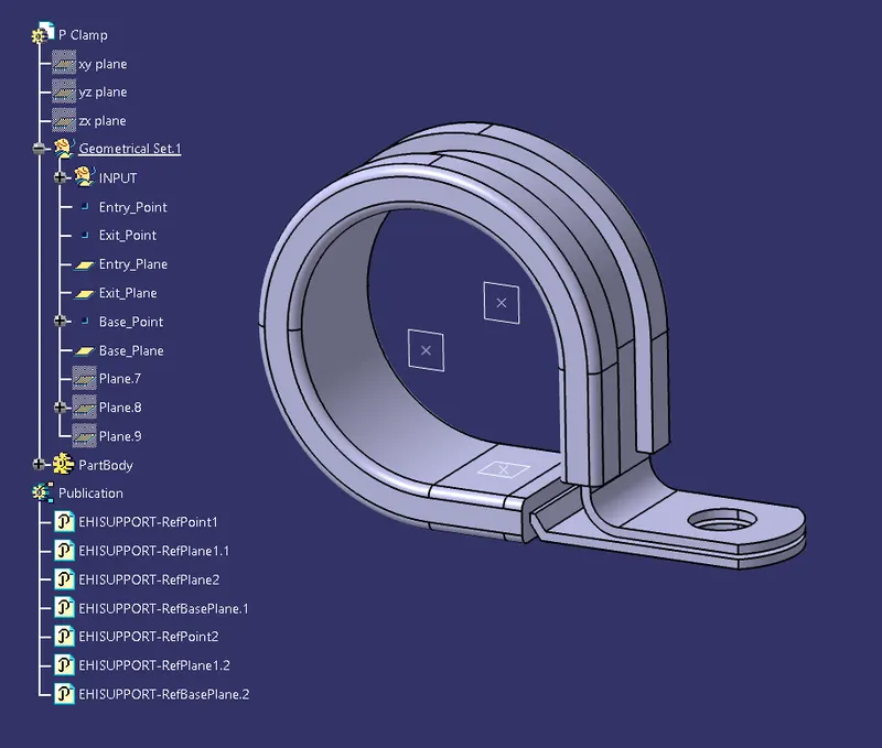
1. Import the downloaded step or igs file into the CATIA mechanical part workbench. Create an entry point on one side and an exit point on the other side of the P-Clip.
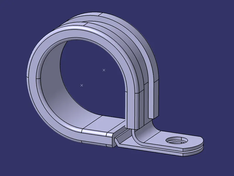
2. Using the Entry & Exit Points create Entry and Exit Plane.
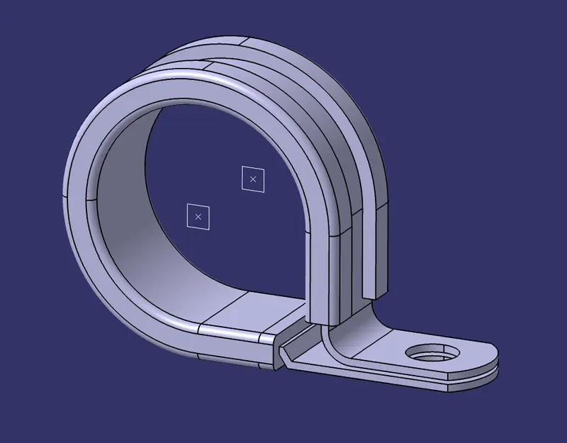
3. Create a Point at the base of the clip & using that point create a Base Plane.
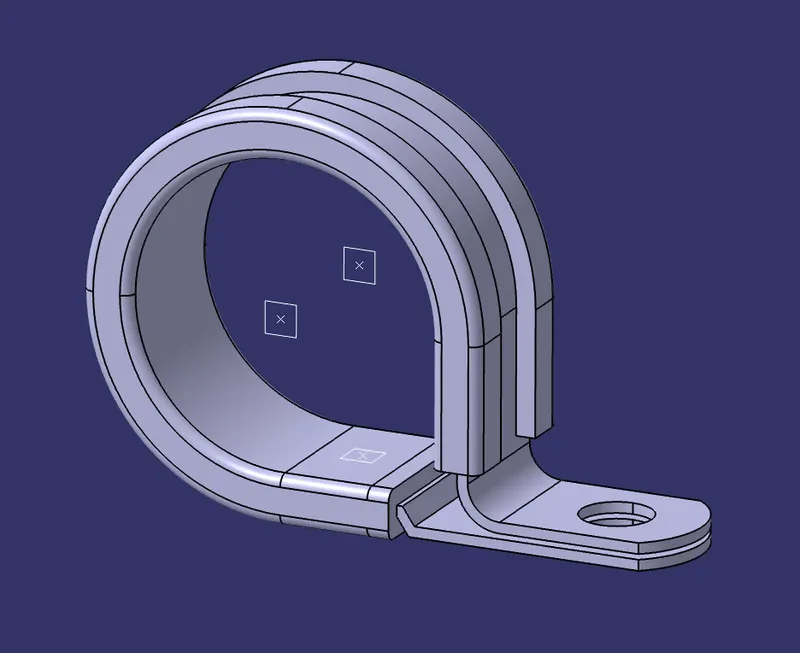
4. Now switch to the Electrical Part Design Workbench and Define the clip as Support Part using the Define Support Part Command. Select the Entry Point as First Point & Entry Plane as First Plane, Select the Exit Plane as Second Plane, and Base Plane as Base Plane.
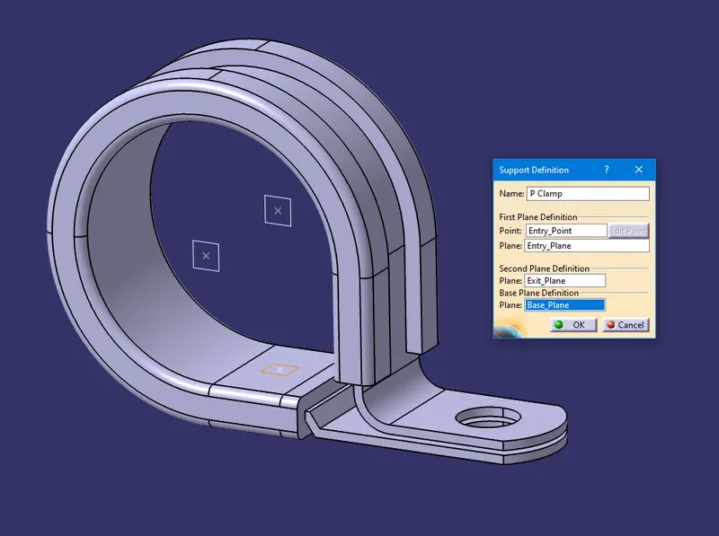
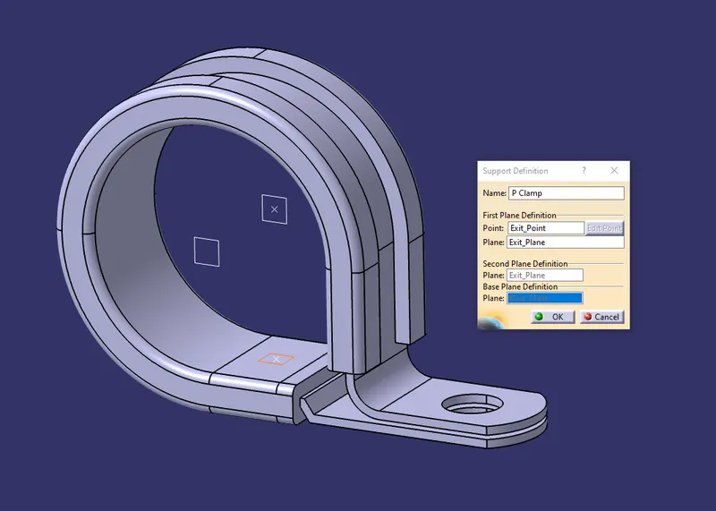
5. Now to create the entry from the opposite side again use the Define Support Part Command. Select the Exit Point as First Point & Exit Plane as First Plane, Select the Entry Plane as Second Plane, and Base Plane as Base Plane.
BACKSHELL CONNECTOR DEFINITION:
The following parameters are required to define Backshell Connector:
- Entry Point
- Backshell Connection Point & Axis
PROCESS:
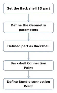
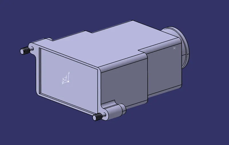
1. Import the downloaded step or igs file into the CATIA mechanical part workbench. Create an entry point on the entry side and a backshell point & plane on the other (Y-Axis facing mating part/direction).
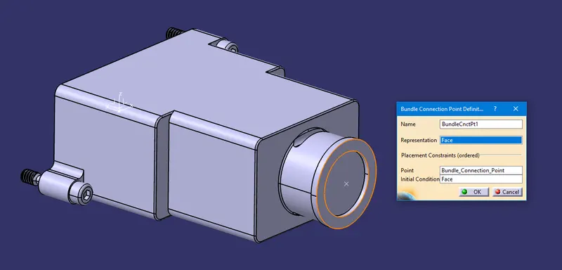
2. Now switch to the Electrical Part Design Workbench, define the connector using Define Backshell Command, and Define the Bundle Connection Point. Face as Representation, Bundle Connection Point as Point, and Same face as Representation for Initial Condition.
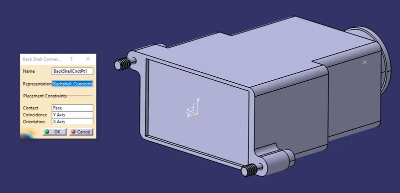
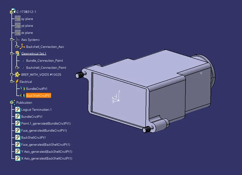
3. Define the Backshell Connection Point. Backshell Connection Point as Representation, Mating Face as Contact, Y-axis as Coincidence, and X-Axis as Orientation.
CORRUGATED TUBES DEFINITION:
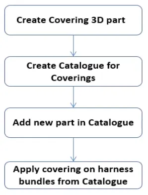
PROCESS:
1. Go to the Electrical Part Design workbench. Select the Define Protection Part and then select the Part Body from the tree. A dialogue box will open.
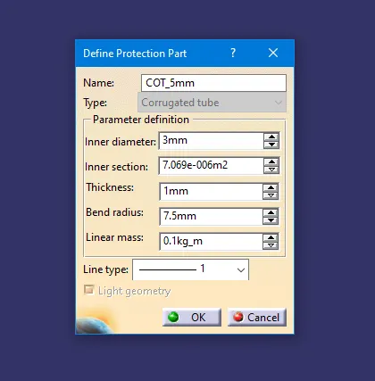
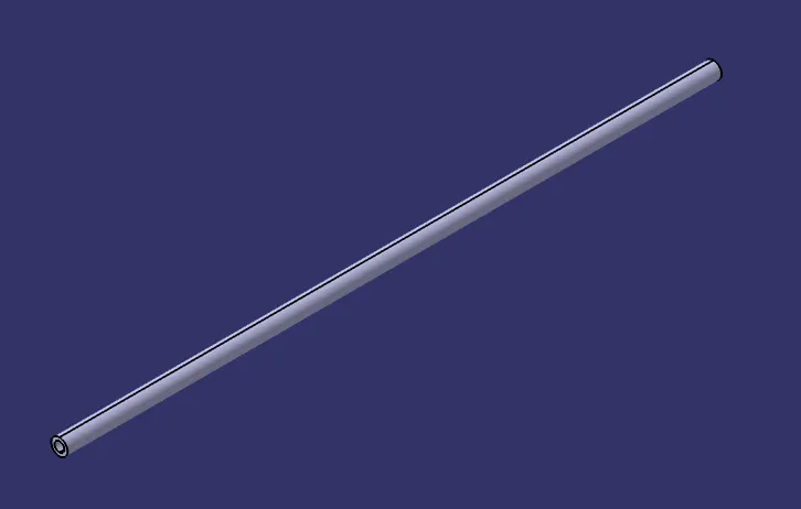
2. Type name of the tube, required inner diameter, thickness, bend radius and click ok. A corrugated Tube part body will be created.
3. Using the Device Storage command store the tube in the respective catalog.
4. Use the same steps to create the Following Corrugated tubes & Add them in Catalogue.
|
Name |
ID (mm) |
OD (mm) |
Thickness (mm) |
|
15mm COT |
12 |
15 |
1.5 |
|
20mm COT |
17 |
20 |
1.5 |
|
35mm COT |
32 |
35 |
1.5 |
|
10mm COT |
7 |
10 |
1.5 |
|
5mm COT |
3 |
5 |
1 |