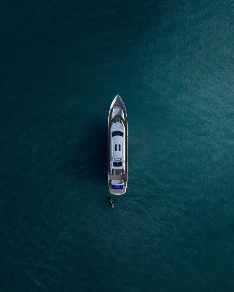
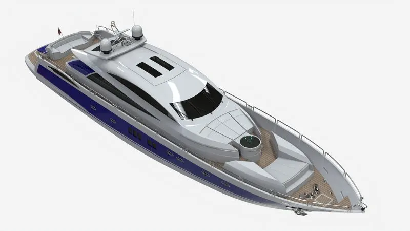
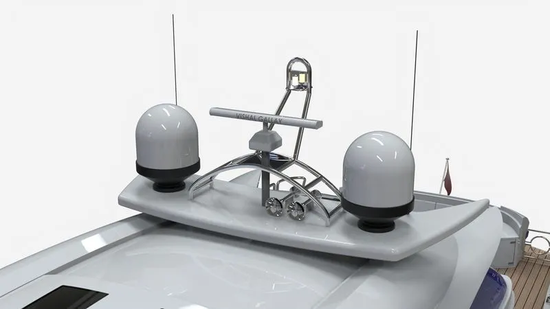
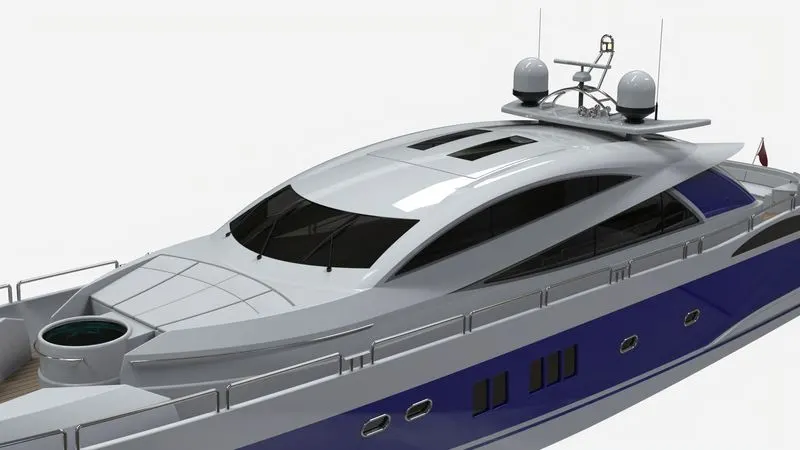
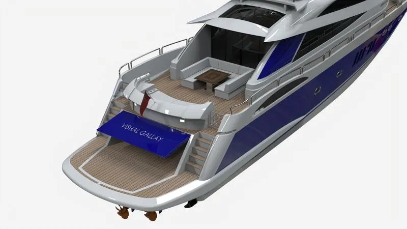
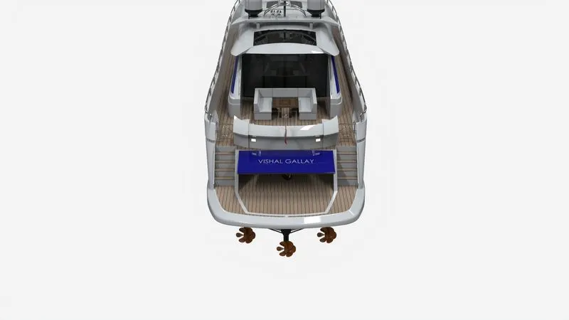
Radar Mast & Final Assembly of Yacht
Title: Modeling, Assembly & Photorealistic Rendering of Sunseeker Predator Yacht.
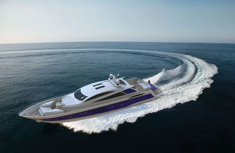
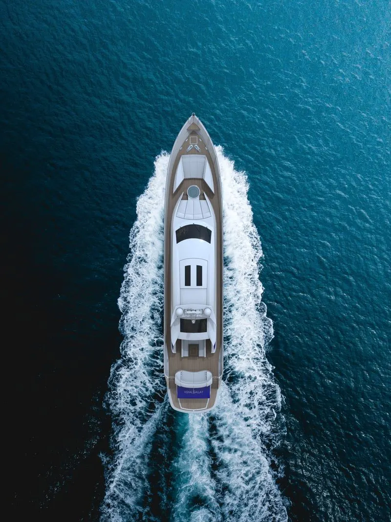
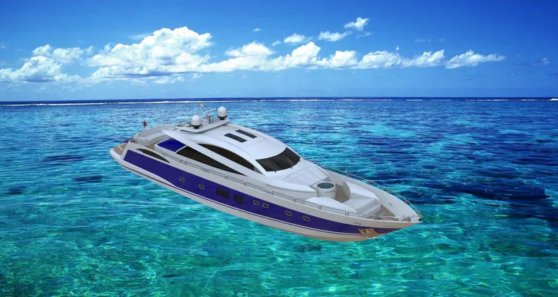
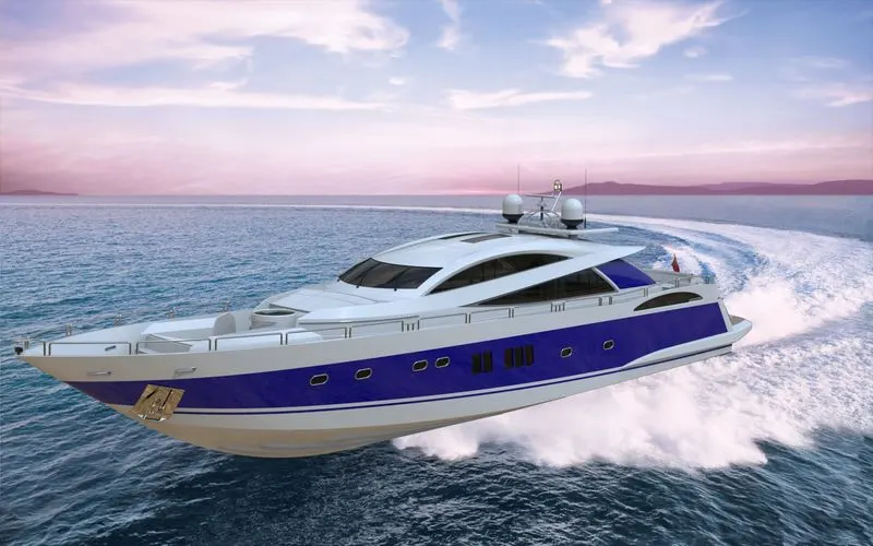
Objective: To model (mainly surfacing) parts of the Sunseeker Predator Yacht using SOLIDWORKS. Later assemble all the parts together, give the proper appearance (color & material) to the parts, adding decals, set up cameras, lights & environment, etc. In the end, render realistic photos of the Yacht using SOLIDWORKS Visualize.
Introduction: This report is about the 3D modeling of the Yacht using SOLIDWORKS. SOLIDWORKS is a 3D CAD software that is used to create 3D CAD models of different types of products which consist of solid modeling, Surfacing, Sheet Metal, Weldments, etc. The modeling of different parts of the yacht is done using various features and given an appropriate appearance individually. Later all the parts are assembled together using proper mates. Then the assembly is rendered with a realistic environment.
Design Methodology/Approach: It is explained by the following flowchart:-
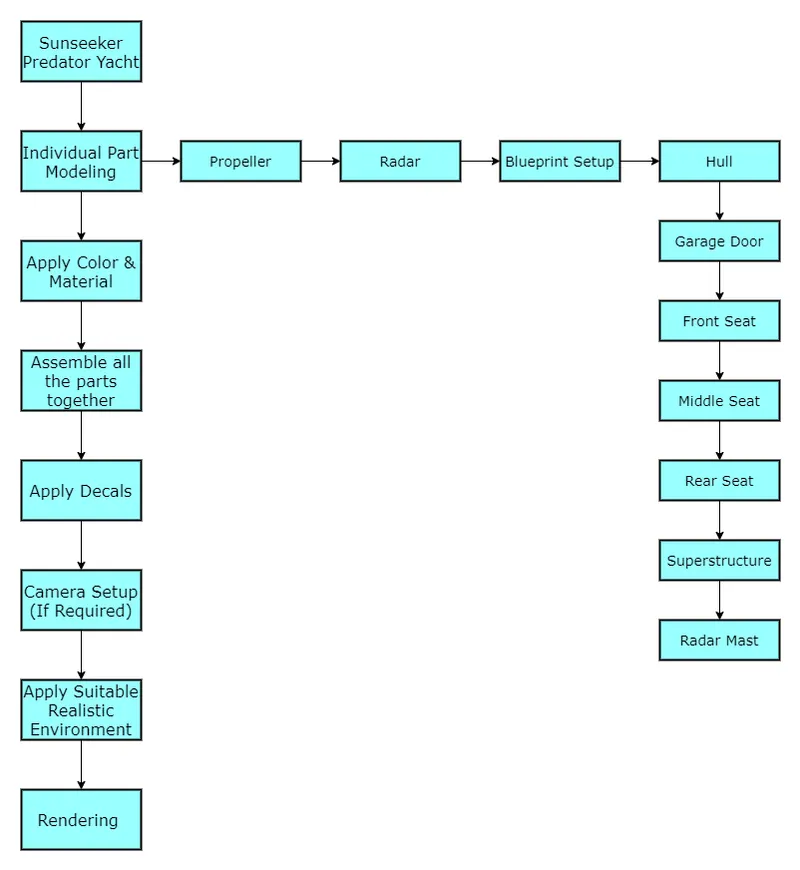
Description:
| COMMANDS USED IN MODELING OF AMERICAN CHOPPER BIKE | ||
| Sr. No. | Comand Name | Function |
| 1 | Boss Extrude | Boss Extrude is a feature tool that allows adding materials to closed sketch profiles or closed drawings. |
| 2 | Extrude Cut | Extrude Cut tool is used to remove material by projecting a sketched section normal to the sketching plane. You can use open or closed sections to create a cut. |
| 3 | Fillets | Fillet creates a rounded internal or external face on the part. You can fillet all edges of a face, selected sets of faces, selected edges, or edge loops. |
| 4 | Lofted Boss | Loft creates a feature by making transitions between profiles. You create a loft using two or more profiles. |
| 5 | Split | It divides a selected body into multiple separate bodies using sketch or surface. |
| 6 | Revolve | Revolve is a feature tool that is used to create a solid 3D model around an axis. You can revolve the sketch around an axis to add materials to it. |
| 7 | Shell | The shell tool hollows out a part, leaves open the faces you select, and creates thin-walled features on the remaining faces. If you do not select any face on the model, you can shell a solid part, creating a closed, hollow model. You can also shell a model using multiple thicknesses. |
| 8 | Mirror | The mirror feature can be used in part and assembly files. it allows you to mirror sketch entities, features, faces, bodies, and components about an axis in sketch and about a plane or face for body and assembly. |
| 9 | Sketch Driven Pattern | Using sketch points within a sketch, you can specify a feature pattern. The seed feature propagates throughout the pattern to each point in the sketch. You can use sketch driven patterns for holes or other feature instances. |
| 10 | Sketch Picture | Sketch Picture includes Insert pictures (.bmp, .gif, .jpg, .jpeg, .tif, .tiff, .wmf, .png, .psd) on a sketch plane, Use pictures as an underlay for creating 2D sketches and Convert raster data to vector data using Autotrace. |
| 11 | Chamfer | The chamfer tool creates a beveled feature on selected edges, faces, or a vertex |
| 12 | Linear Pattern | It is used to pattern a feature or a part along a straight line. |
| 13 | Surface Loft | Surface Loft is surfaces generated by multiple 3D Curves or existing edges creating a smooth tangency between the selected curves. Match Points are created between each selection denoting the orientation and path of the loft surface. |
| 14 | Circular Pattern | It is used to pattern a feature or a part along a Circular path. |
| 15 | Sweep | The Sweep tool is used to create solid/surface features by sweeping closed-loop sketches along the selected trajectory. This tool is generally used when we need to create tubes/bars following a curvature. |
| 16 | Project Curve | You can project a sketched curve onto a model face to create a 3D curve. You can also create a 3D curve that represents the intersection of two extruded surfaces generated by creating sketches on two intersecting planes. You can create multiple closed or open-contour projected curves from a single sketch. You can also use 3D sketches as input for the Projected Curve tool. |
| 17 | Surface Extrude | You can create extruded surfaces from models that include 2D or 3D faces and knit the extruded surfaces to surrounding features. |
| 18 | Surface Fill | The Surface Fill feature constructs a surface patch with any number of sides, within a boundary defined by existing model edges, sketches, or curves, including composite curves. You can use this feature to construct a surface to fill a gap in a model. |
| 19 | Surface Trim | You can use a surface, plane, or sketch as a trim tool to trim intersecting surfaces. You can also use a surface in conjunction with additional surfaces, as mutual trim tools. |
| 20 | Boundary Surface | The boundary surface feature lets you create surfaces that can be tangent or curvature continuous in both directions (all sides of the surface). In most cases, this delivers a higher quality result than the loft tool. |
| 21 | Surface Knit | Use the Knit Surface tool to combine two or more faces and surfaces into one. |
| 22 | Surface Offset | The Offset Surface tool creates a new surface body from an existing set of faces. The faces may be solid or surface faces. |
| 23 | Surface Extend | You can extend a surface by selecting an edge, multiple edges, or a face. |
| 24 | Surface Cut | You can cut a solid model by removing material with a surface or plane. With multibody parts, you can select which bodies to keep. |
| 25 | Dome | It is used to create Concave or Convex Dome by selecting one or more planer or non-planer faces. |
| 26 | Helix and Spiral | You can create a helix or spiral curve in a part. The curve can be used as a path or guide curve for a swept feature, or a guide curve for a lofted feature. |
| 27 | Split Line | The Split Line tool projects an entity (sketch, solid, surface, face, plane, or surface spline) to surfaces, or curved or planar faces. It divides a selected face into multiple separate faces. You can split curves on multiple bodies with one command. |
| 28 | Surface Sweep | Surface Sweep is the feature that helps sweep a profile as a surface along a closed or open path. |
| 29 | Ruled Surface | The Ruled Surface command creates surfaces that extend out in a specified direction from selected edges. |
| 30 | Thicken | Creates a solid feature by thickening one or more adjacent surfaces. |
1. Propeller: A propeller is a fan-like structure that propels the ship by rotating on its axis using the power generated and transmitted by the main engine of the ship.
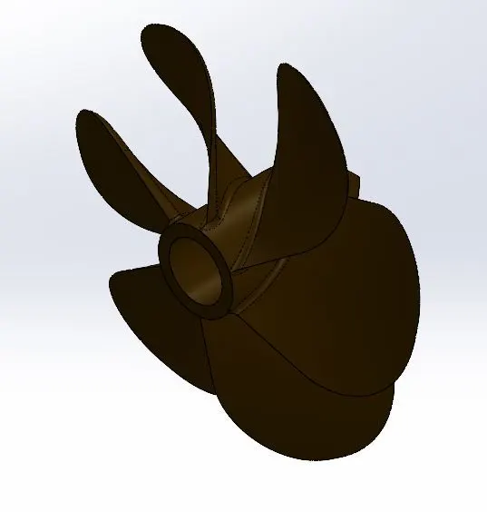
Following are the tools and features used while designing:-
- Sketch
- Sketch Picture (BluePrint)
- Line
- Spline
- Circle
- Offset
- Plane
- Constrains (Horizontal, Vertical, Tangent, Coincident, Pierce, etc)
- Fillet
- Revolve
- Lofted Boss
- Extruded Cut
- Circular Pattern
2. Blueprint Setup: It acts as a reference for the part designing. The sketch picture is imported and adjusted to match the dimensions of the part to be designed.
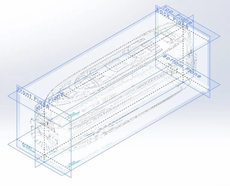
Following are the tools and features used while designing:-
- Sketch
- Sketch Picture (BluePrint)
- Plane
3. Radar: It gives navigation and detects other ships & land obstacles to avoid a collision.
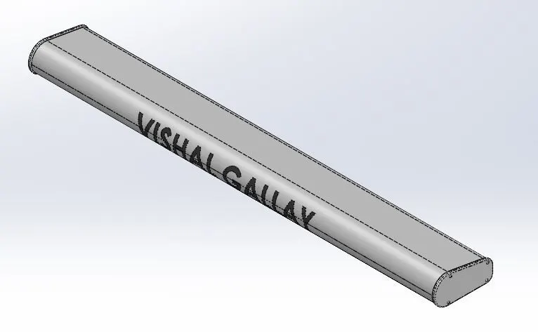
Following are the tools and features used while designing:-
- Sketch
- Sketch Picture (BluePrint)
- Line
- Offset
- Plane
- Constrains (Horizontal, Vertical, Tangent, Coincident, Pierce, etc)
- Fillet
- Sketch Driven Pattern
- Mirror
- Extruded Cut
- Boss Extrude
- Split line
- Text
4. Hull: It is the major and watertight part of the yacht. The hull can be open at the top or can be fully/partially covered with a deck. It also protects the cargo, machinery, and accommodation spaces of the ship from the weather, flooding, and structural damage.
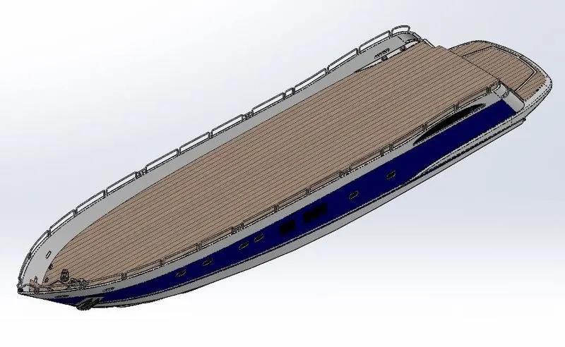
Following are the tools and features used while designing:-
- Sketch
- Sketch Picture (BluePrint)
- Circle
- Line
- Spline
- Offset
- Plane
- Constrains (Horizontal, Vertical, Tangent, Coincident, Pierce, etc)
- Surface Sweep
- Fillet
- Chamfer
- Helix and Spiral
- Linear Pattern
- Offset Surface
- Split
- Surface Trim
- Boundary Surface
- Split Line
- Surface Extrude
- Surface Loft
- Project Curve
- Surface Cut
- Surface Knit
- Surface Fill
- Surface Extend
- Mirror
- Swept Boss
- Thin Extrude
- Thin Extrude Cut
- Boss Extrude
- Extruded Cut
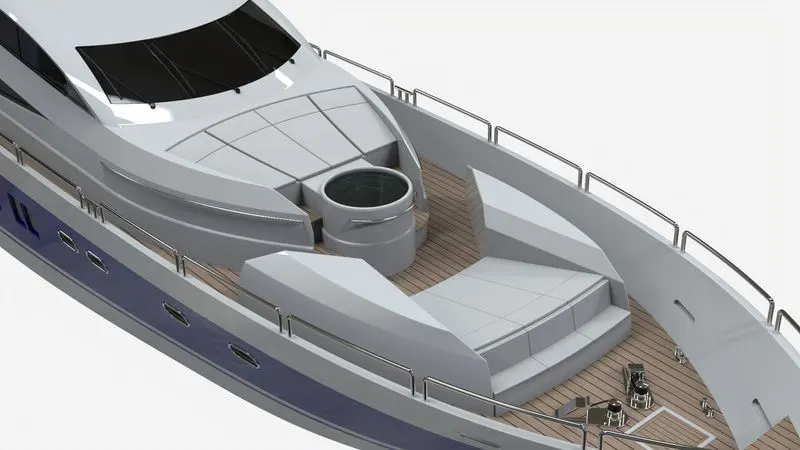
5. Garage Door: It is a garage door at the rear side of the yacht.
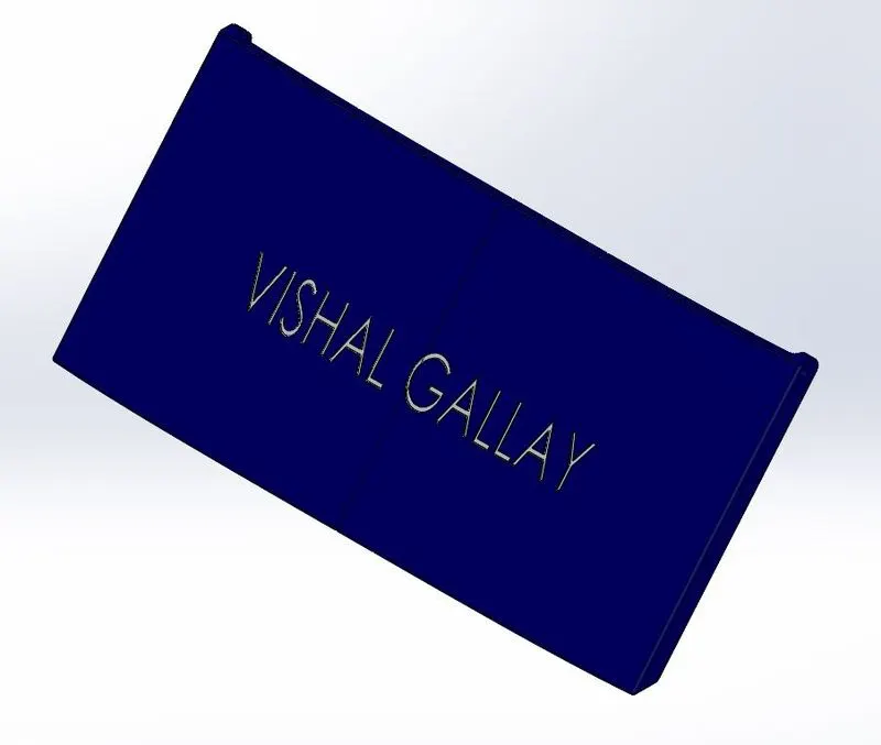
Following are the tools and features used while designing:-
- Sketch
- Sketch Picture (BluePrint)
- Line
- Offset
- Plane
- Constrains (Horizontal, Vertical, Tangent, Coincident, Pierce, etc)
- Fillet
- Shell
- Mirror
- Extruded Cut
- Boss Extrude
- Text
6. Front Seat: It is at the front of the yacht.
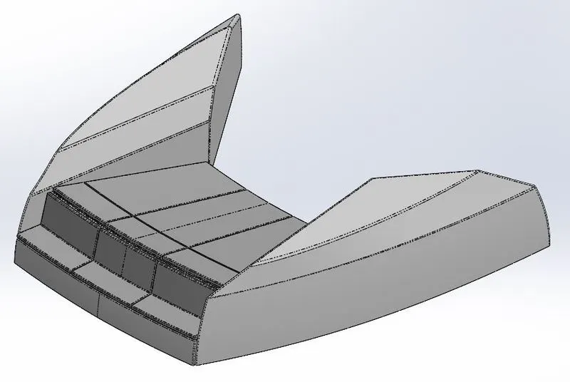
Following are the tools and features used while designing:-
- Sketch
- Sketch Picture (BluePrint)
- Line
- Spline
- Offset
- Plane
- Constrains (Horizontal, Vertical, Tangent, Coincident, Pierce, etc)
- Surface Sweep
- Fillet
- Chamfer
- Surface Trim
- Surface Extrude
- Surface Loft
- Surface Knit
- Surface Fill
- Surface Extend
- Mirror
- Extruded Cut
7. Middle Seat: It is at the middle of the yacht.
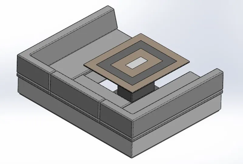
Following are the tools and features used while designing:-
- Sketch
- Sketch Picture (BluePrint)
- Line
- Offset
- Plane
- Constrains (Horizontal, Vertical, Tangent, Coincident, Pierce, etc)
- Fillet
- Chamfer
- Mirror
- Extruded Cut
- Boss Extrude
8. Rear Seat: It is at the rear of the yacht.
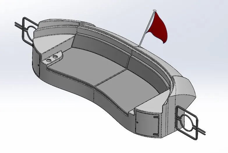
Following are the tools and features used while designing:-
- Sketch
- Sketch Picture (BluePrint)
- Line
- Circle
- Spline
- Offset
- Plane
- Constrains (Horizontal, Vertical, Tangent, Coincident, Pierce, etc)
- Surface Sweep
- Fillet
- Chamfer
- Ruled Surface
- Offset Surface
- Surface Trim
- Surface Extrude
- Surface Loft
- Surface Knit
- Surface Fill
- Surface Extend
- Mirror
- Extruded Cut
- Boss Extrude
- Swept Boss
- Revolve
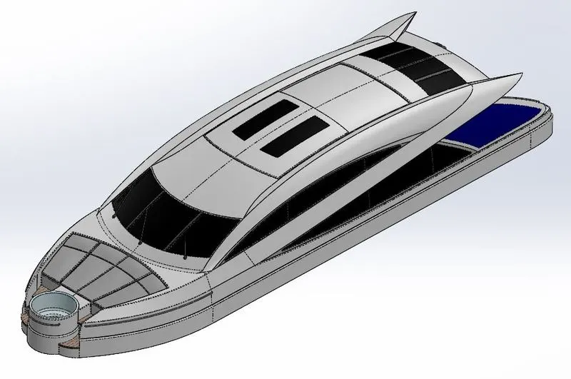
9. Superstructure: A superstructure is an upward extension of an existing structure above a baseline. The size of the superstructure has a great influence on the mobility of the vessels. they are designed in a manner so that they add value and hinder speed and mobility. It also facilitates the driver's cabin, accommodation rooms, and other rooms.
Following are the tools and features used while designing:-
- Sketch
- Sketch Picture (BluePrint)
- Circle
- Line
- Spline
- Offset
- Plane
- Constrains (Horizontal, Vertical, Tangent, Coincident, Pierce, etc)
- Surface Sweep
- Fillet
- Chamfer
- Offset Surface
- Split
- Surface Trim
- Boundary Surface
- Split Line
- Surface Extrude
- Surface Loft
- Project Curve
- Ruled Surface
- Surface Knit
- Surface Fill
- Surface Extend
- Mirror
- Swept Boss
- Boss Extrude
- Extruded Cut
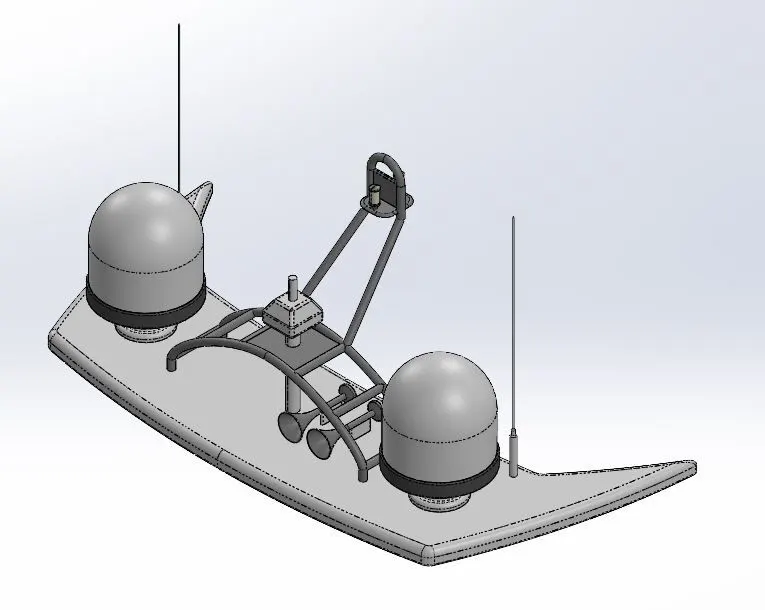
10. Radar Mast: The mast of a ship is a tall spar, or arrangement of spars, erected more or less vertically on the centerline of a ship or boat. Its purpose is to give necessary height to a navigation light, look out position, signal yard, radio aerial, or signal lamp.
Following are the tools and features used while designing:-
- Sketch
- Sketch Picture (BluePrint)
- Circle
- Line
- Spline
- Offset
- Plane
- Constrains (Horizontal, Vertical, Tangent, Coincident, Pierce, etc)
- Fillet
- Shell
- Mirror
- Swept Boss
- Boss Extrude
- Extruded Cut
- Revolve
- Dome
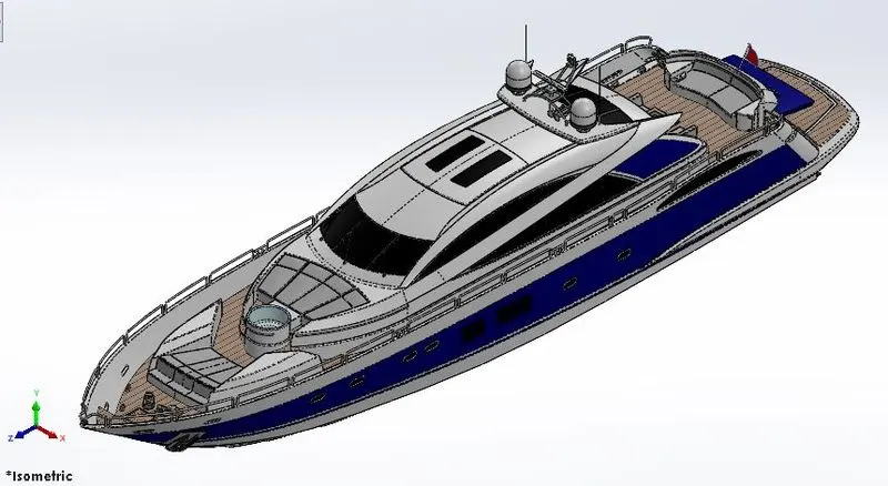
Assembly of Sunseeker Predator Yacht
After modeling all the parts individually, all the parts are assembled together using appropriate mates.
Following are the different mates which are used for assembly:-
- Coincident Mate
- Distance Mate
- Tangent Mate
- Parallel Mate
- Concentric Mate
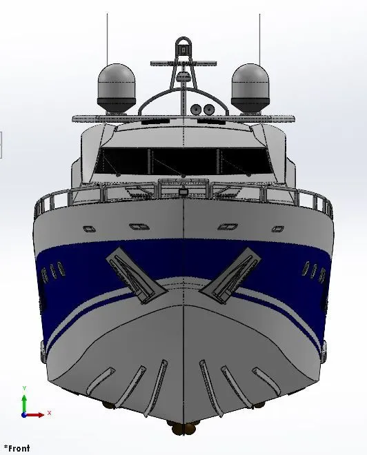
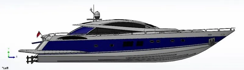
Photorealistic Rendering and Applying Decal
After the complete assembly of the yacht, Decals are applied to the individual part on which it is required. Then Appropriate environment and Cameras at different angles are set. Lighting, Brightness, Reflections, and other parameters are also fine-tuned if you are not satisfied with the default settings. When everything is set rendering is done with different environments, colors, and angles.