Week 8 - Challenge 3 - Switch Bezel Design
SWITCH BEZEL DESIGN
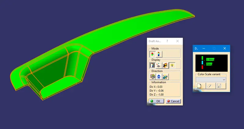
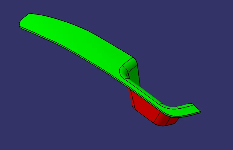
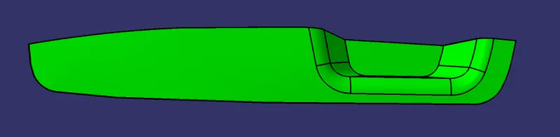
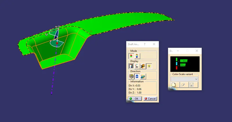
OBJECTIVE: To perform draft analysis to check if the part has the given draft on its all faces, to determine the tooling axis and design component using the class-A surface as a reference.
DRAFT: Draft is a tool used in CATIA to make the faces taper with respect to the tooling axis. Tooling Axis is the direction of mold part ejection.
Why draft is necessary?
When developing parts for plastic injection molding, applying draft (or a taper) to the faces of the part is critical to improving the moldability of your part. Without it, parts run the risk of poor cosmetic finishes and may bend, break, or warp due to molding stresses caused by the plastic cooling.
Draft Ange Recommendations:
- 3° is Nominal Draft.
- 0.5° is a minimum draft which increases the cost of manufacturing.
- 7° for Textured Faces.
Procedure:
Draft analysis:
- First, Check the Class A surface that it has no gaps. To check, use JOIN or BOUNDARY command. In JOIN, it will highlight the surfaces individually if there is more than one. In BOUNDARY, it will create a boundary line along all the edges of the surface and after hiding the Class A Surface we can check if there is any unexpected line.
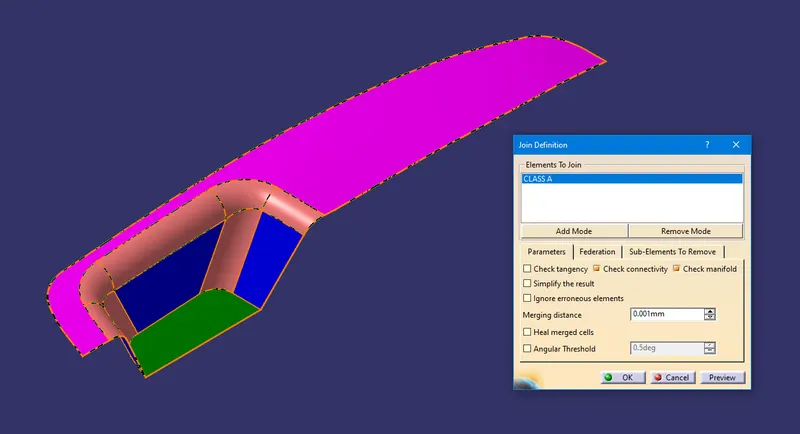
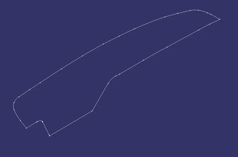
- Now we analyze the best possible Tooling Direction using the X/Y/Z planes.
- Extract Base Surface.

- Create a center point on the surface and create a new axis system.

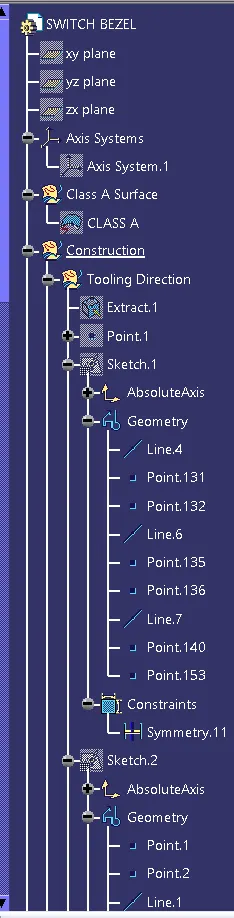
- Start a positioned sketch on YZ Plane and create an intersection of the surface. With the help of the intersection, line create 2 lines and from them create a bisection line.
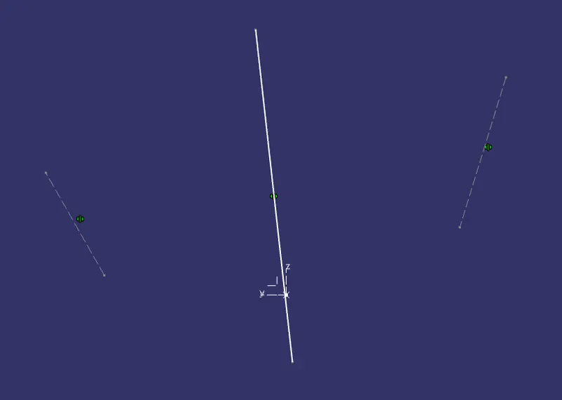
- Do the same procedure on ZX Plane. As there is no second line to intersect just give the tooling axis angle dimension.
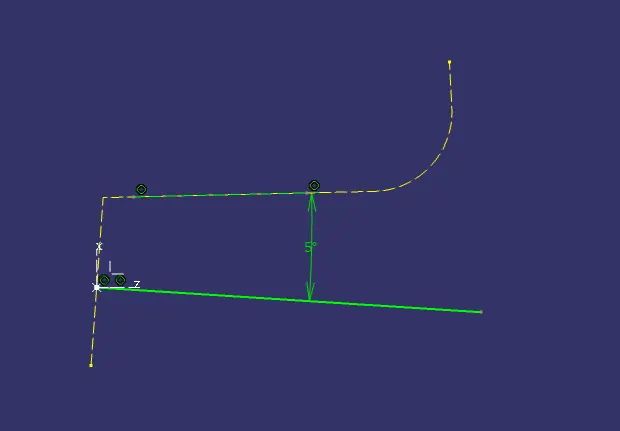
- Tooling Axis
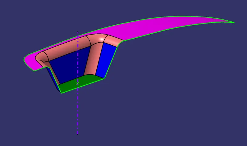
CLASS A SURFACE DRAFT ANALYSIS
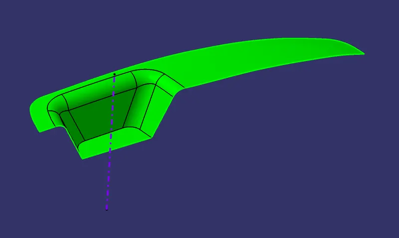
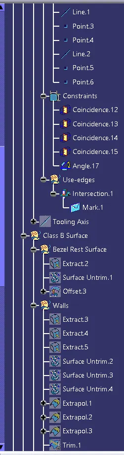
CLASS B SURFACE
Bezel Rest Surface
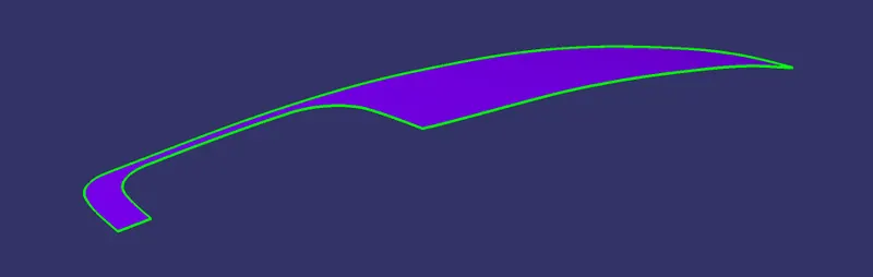
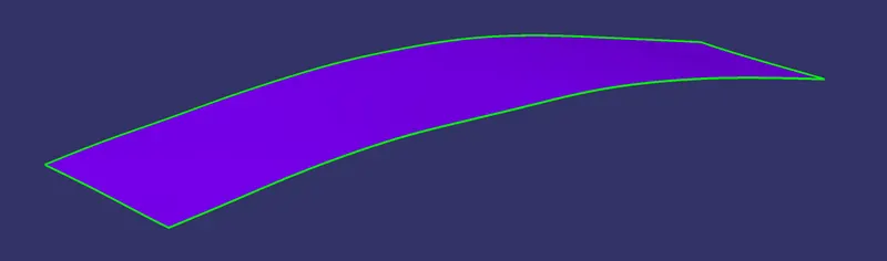
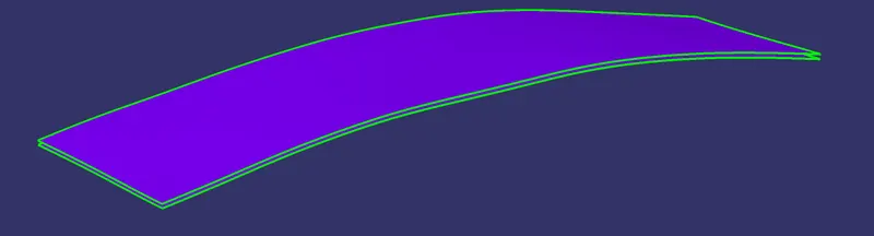
Walls




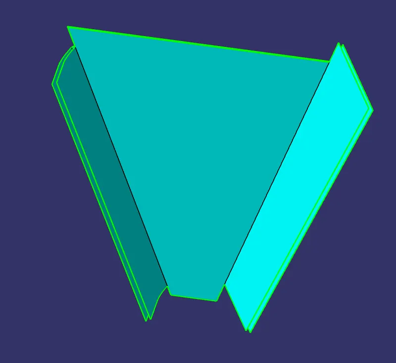
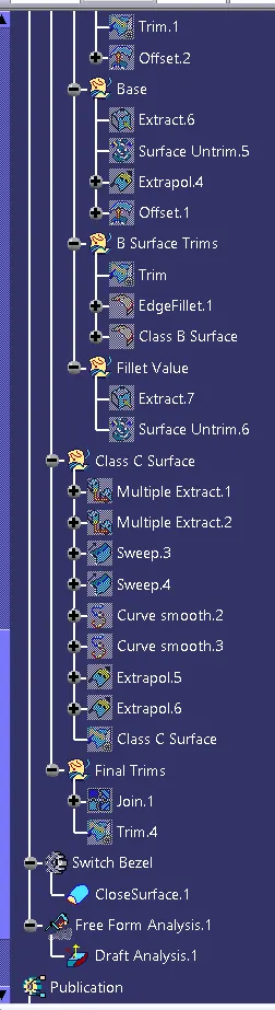
Base

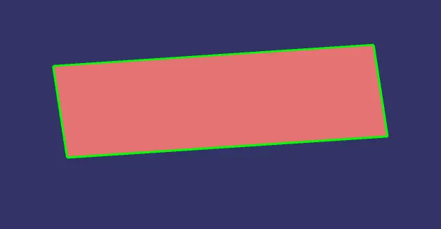


B Surface Trims
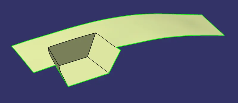
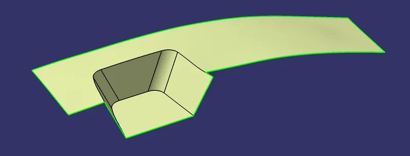
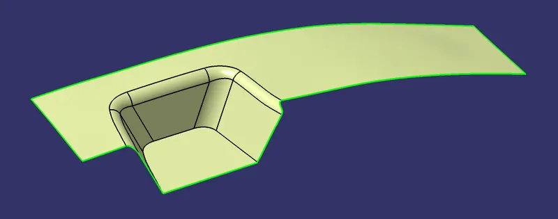
CLASS C SURFACE

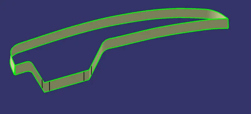
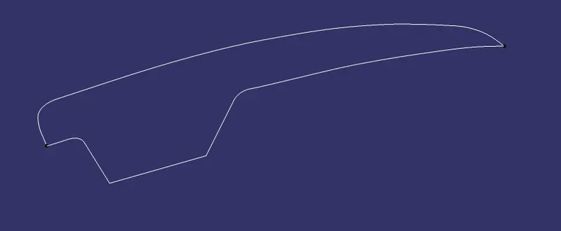
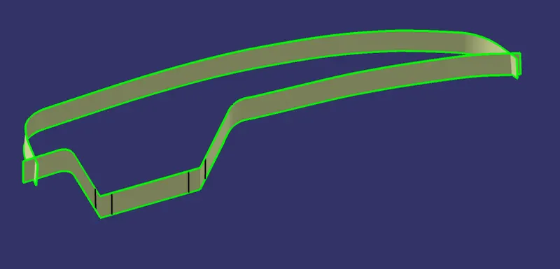
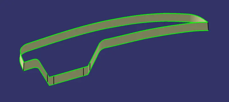
FINAL TRIMS
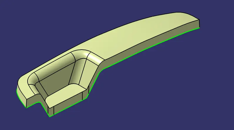
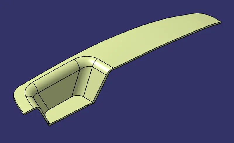
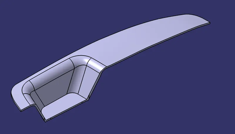
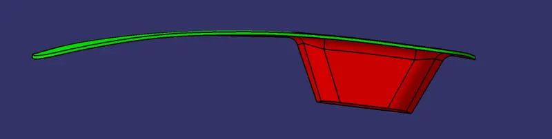
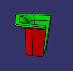
Draft analysis