Photo Realistic Rendering
Title: Modeling, Assembly & Photorealistic Rendering of American Chopper.
Objective: To model parts of the American Chopper Bike using SOLIDWORKS. Later assemble all the parts together, give the proper appearance (color & material) to the parts, adding decals, set up cameras, lights & environment, etc. In the end, render realistic photos of the bike using SOLIDWORKS Visualize.
Introduction: This report is about 3D modeling of the American Chopper Bike using SOLIDWORKS. SOLIDWORKS is a 3D CAD software that is used to create 3D CAD models of different types of products which consist of solid modeling, Surfacing, Sheet Metal, Weldments, etc. The modeling of different parts of the bike is done using various features and given an appropriate appearance individually. Later all the parts are assembled together using proper mates. Then the assembly is rendered with realistic environment.
Design Methodology/Approach: It is explained by the following flowchart:-
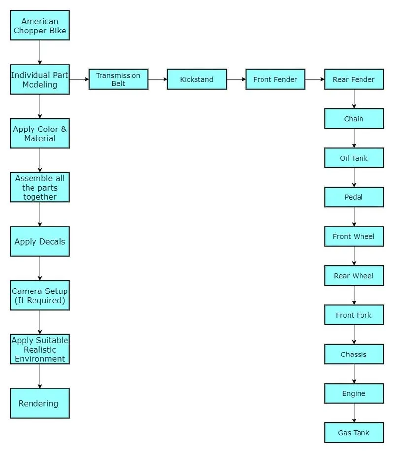
Description:
| COMMANDS USED IN MODELING OF AMERICAN CHOPPER BIKE | ||
| Sr. No. | Comand Name | Function |
| 1 | Boss Extrude | Boss Extrude is a feature tool that allows adding materials to closed sketch profiles or closed drawings. |
| 2 | Extrude Cut | Extrude Cut tool is used to remove material by projecting a sketched section normal to the sketching plane. You can use open or closed sections to create a cut. |
| 3 | Fillets | Fillet creates a rounded internal or external face on the part. You can fillet all edges of a face, selected sets of faces, selected edges, or edge loops. |
| 4 | Lofted Boss | Loft creates a feature by making transitions between profiles. You create a loft using two or more profiles. |
| 5 | Split | It divides a selected body into multiple separate bodies using sketch or surface. |
| 6 | Revolve | Revolve is a feature tool that is used to create a solid 3D model around an axis. You can revolve the sketch around an axis to add materials to it. |
| 7 | Shell | The shell tool hollows out a part, leaves open the faces you select, and creates thin-walled features on the remaining faces. If you do not select any face on the model, you can shell a solid part, creating a closed, hollow model. You can also shell a model using multiple thicknesses. |
| 8 | Mirror | The mirror feature can be used in part and assembly files. it allows you to mirror sketch entities, features, faces, bodies, and components about an axis in sketch and about a plane or face for body and assembly. |
| 9 | Curve Driven Pattern | It is used to pattern a feature or a part along a curve. |
| 10 | Combine | It is used to Combine multiple bodies into a single body. |
| 11 | Chamfer | The chamfer tool creates a beveled feature on selected edges, faces, or a vertex |
| 12 | Linear Pattern | It is used to pattern a feature or a part along a straight line. |
| 13 | Revolve Cut | Revolved Cut is a feature tool that is used to create Cut in a 3D model around an axis. You can revolve the sketch around an axis to subtract materials from it. |
| 14 | Circular Pattern | It is used to pattern a feature or a part along a Circular path. |
| 15 | Sweep | The Sweep tool is used to create solid/surface features by sweeping closed-loop sketches along the selected trajectory. This tool is generally used when we need to create tubes/bars following a curvature. |
| 16 | Project Curve | You can project a sketched curve onto a model face to create a 3D curve. You can also create a 3D curve that represents the intersection of two extruded surfaces generated by creating sketches on two intersecting planes. You can create multiple closed or open-contour projected curves from a single sketch. You can also use 3D sketches as input for the Projected Curve tool. |
| 17 | Composite Curve | You can create composite curves by combining curves, sketch geometry, and model edges into a single curve. Use a composite curve as a guide curve when creating a loft or a sweep. |
| 18 | Swept Cut | swept cut is a features tool, mainly used to cut a solid model or part by sweeping a completely closed profile along an open or closed path. To use swept cut, you should need a closed profile and open or closed path, which may be a line, helix, and circle, rectangular or arc, etc. |
| 19 | Surface Trim | You can use a surface, plane, or sketch as a trim tool to trim intersecting surfaces. You can also use a surface in conjunction with additional surfaces, as mutual trim tools. |
| 20 | Boundary Surface | The boundary surface feature lets you create surfaces that can be tangent or curvature continuous in both directions (all sides of the surface). In most cases, this delivers a higher quality result than the loft tool. |
| 21 | Surface Knit | Use the Knit Surface tool to combine two or more faces and surfaces into one. |
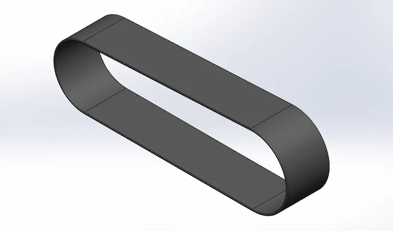
1. Transmission Belt: A Transmission belt is used to transmit the power. In bikes, it is used to transmit power from the engine to the rear wheel.
Following are the tools and features used while designing:-
- Sketch
- Circles
- Lines
- Offset
- Constrains (Tangent, Horizontal, Coincident, etc)
- Boss Extrude
- Fillet
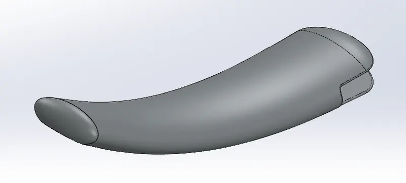
2. Kickstand: Kickstand also known as Sidestand. It keeps the bike upright while the bike is at rest.
Following are the tools and features used while designing:-
- Sketch
- Circle
- Line
- Elipse
- Rectangle
- Spline
- Constrains (Pierce, Horizontal, Coincident, Vertical, Midpoint, etc)
- Plane
- Loft
- Dome
- Cut Extrude
- Split
- Boss Extrude
- Fillet
3. Front Fender: Its primary function is to protect the Rider, Engine Block, and other parts from Sand, Mud, Rocks, Liquids, and other road sprays which are thrown into the air by rotating tire due to centrifugal force.
Following are the tools and features used while designing:-
- Sketch
- Circle
- Line
- Spline
- Constrains (Horizontal, Coincident, Vertical, Midpoint, Symmetric, etc)
- Revolve
- Split
- Fillet
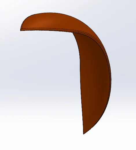
4. Rear Fender: Its primary function is to protect the Rider, Engine Block, and other parts from Sand, Mud, Rocks, Liquids, and other road sprays which are thrown into the air by rotating tire due to centrifugal force.
Following are the tools and features used while designing:-
- Sketch
- Circle
- Line
- Constrains (Horizontal, Coincident, Vertical, Midpoint, etc)
- Revolve
- Split
- Fillet
- Shell
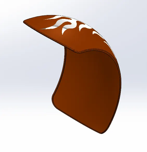
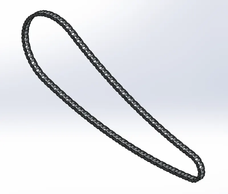
5. Chain: Chain Transmits the motion from the gearbox to the rear wheel sprocket.
Following are the tools and features used while designing:-
- Sketch
- Circle
- Line
- Blocks
- Spline
- Constrains (Pierce, Horizontal, Vertical, Tangent, Coincident, Midpoint, etc)
- Curve Driven Pattern
- Cut Extrude
- Delete Body
- Boss Extrude
- Fillet
- Mirror
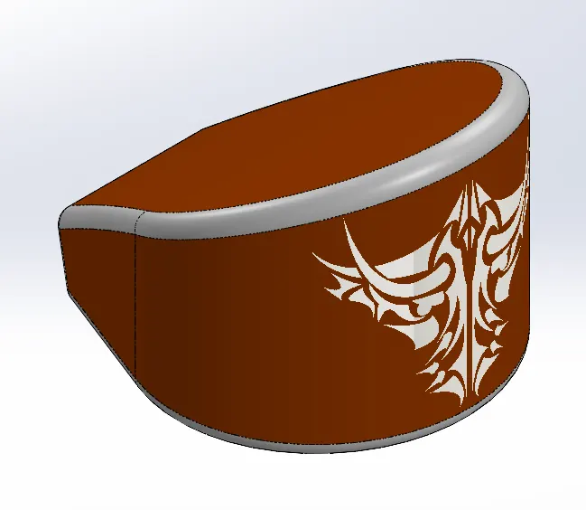
6. Oil Tank: The oil tank stores lubricating oil for the Engine. For smooth and efficient running the engine requires lubrication. The oil tank supplies lubrication oil to the engine and other parts of the bike.
Following are the tools and features used while designing:-
- Sketch
- Circle
- Line
- Spline
- Constrains (Horizontal, Vertical, Tangent, Coincident, Midpoint, Symmetric, etc)
- Boss Extrude
- Fillet
- Combine
- Shell
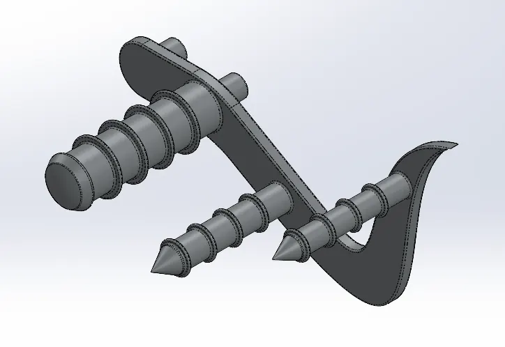
7. Pedal: The bike rider rests their feet on the pedal while ridding and also controls the Gear & Rear Brake.
Following are the tools and features used while designing:-
- Sketch
- Circle
- Line
- Spline
- Constrains (Horizontal, Vertical, Tangent, Coincident, Parallel, Equal, Symmetric, etc)
- Boss Extrude
- Fillet
- Revolve
- Dome
- Chamfer
- Linear Pattern
8. Front Wheel: The front is a freewheel that is mounted to the Front Fork. In this bike, the front wheel consists of Tyre, Alloy Rim, and Disk Brake.
Following are the tools and features used while designing:-
- Sketch
- Circle
- Line
- Spline
- Arc
- Offset
- Convert Entities
- Constrains (Horizontal, Vertical, Tangent, Coincident, Parallel, Equal, Symmetric, etc)
- Boss Extrude
- Fillet
- Revolve
- Revolve Cut
- Circular Pattern
- Extrude Cut
- Combine
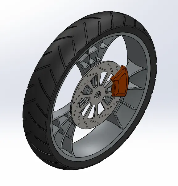
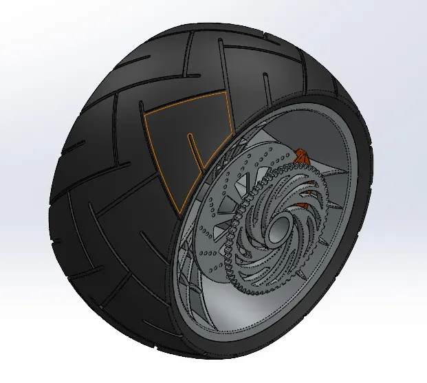
9. Rear Wheel: The Rear is a driving wheel that is mounted to the Chassis. In this bike, the front wheel consists of Tyre, Alloy Rim, Sprocket, and Disk Brake. The Chain from the engine is connected to the sprocket of the wheel.
Following are the tools and features used while designing:-
- Sketch
- Circle
- Line
- Spline
- Arc
- Offset
- Convert Entities
- Constrains (Horizontal, Vertical, Tangent, Coincident, Parallel, Equal, Symmetric, etc)
- Boss Extrude
- Fillet
- Revolve
- Revolve Cut
- Circular Pattern
- Extrude Cut
- Combine
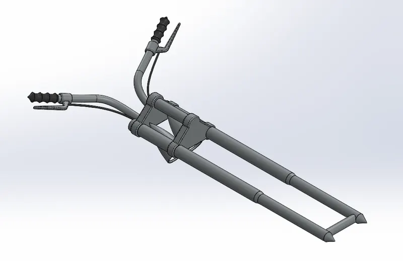
10. Front Fork: Front Fork gives the desired direction to the bike. It is connected to the Chassis and Front Wheel is connected to the fork. The Handgrip, brake & Clutch is connected to the Handle which is also connected to the Front Fork.
Following are the tools and features used while designing:-
- Sketch
- Circle
- Line
- Spline
- Arc
- Offset
- Convert Entities
- Plane
- Constrains (Horizontal, Vertical, Tangent, Coincident, Parallel, Equal, Symmetric, etc)
- Boss Extrude
- Fillet
- Revolve
- Revolve Cut
- Linear Pattern
- Extrude Cut
- Combine
- Sweep
- Move Body
- Project Curve
- Mirror
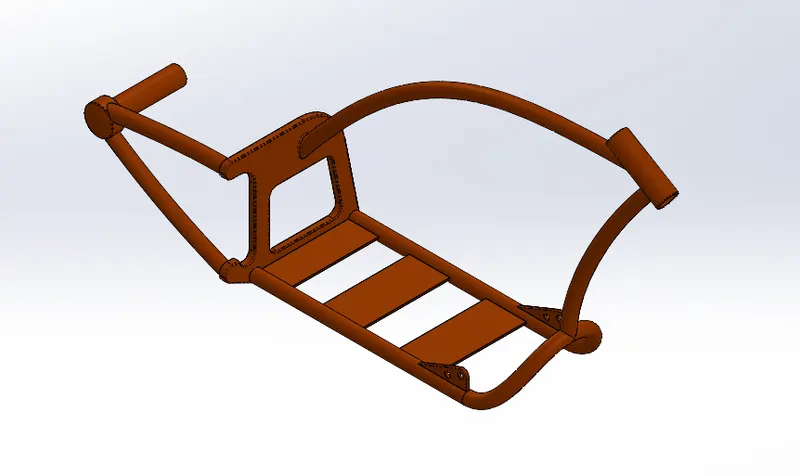
11. Chassis: The chassis is the main part of the bike. All the parts of the bike are mounted on the chassis.
Following are the tools and features used while designing:-
- Sketch
- Sketch Picture (BluePrint)
- Circle
- Line
- Spline
- Arc
- Offset
- Convert Entities
- Plane
- Constrains (Horizontal, Vertical, Tangent, Coincident, Parallel, Equal, Pierce, etc)
- Boss Extrude
- Fillet
- Revolve
- Extrude Cut
- Combine
- Sweep
- Split
- Project Curve
- Mirror
- Dome
- Chamfer
12. Engine: The engine is the heart of the bike. It contains Gear Box, Piston Cylinders, Exhaust Pipes, and Spark Plugs. The engine is mounted on the Chassis.
Following are the tools and features used while designing:-
- Sketch
- Sketch Picture (BluePrint)
- Circle
- Line
- Spline
- Arc
- Offset
- Convert Entities
- Plane
- Constrains (Horizontal, Vertical, Tangent, Coincident, Equal, Pierce, etc)
- Boss Extrude
- Fillet
- Revolve
- Extrude Cut
- Circular Pattern
- Linear Pattern
- Mirror
- Combine
- Sweep
- Split
- Project Curve
- Mirror
- Dome
- Composite Curve
- Chamfer
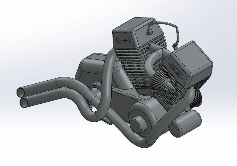
13. Gas Tank: Gas Tank stores the fuel and supplies it to the engine.
Following are the tools and features used while designing:-
- Sketch
- Sketch Picture (BluePrint)
- Circle
- Line
- Spline
- Offset
- Plane
- Constrains (Horizontal, Vertical, Tangent, Coincident, Pierce, etc)
- Surface Sweep
- Fillet
- Swept Cut
- Surface Trim
- Boundary Surface
- Split Line
- Surface Extrude
- Surface Loft
- Project Curve
- Surface Knit
- Composite Curve
- Shell
- Mirror
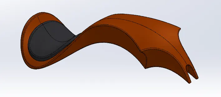
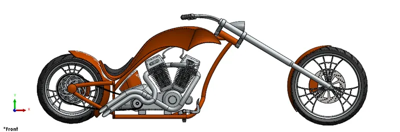
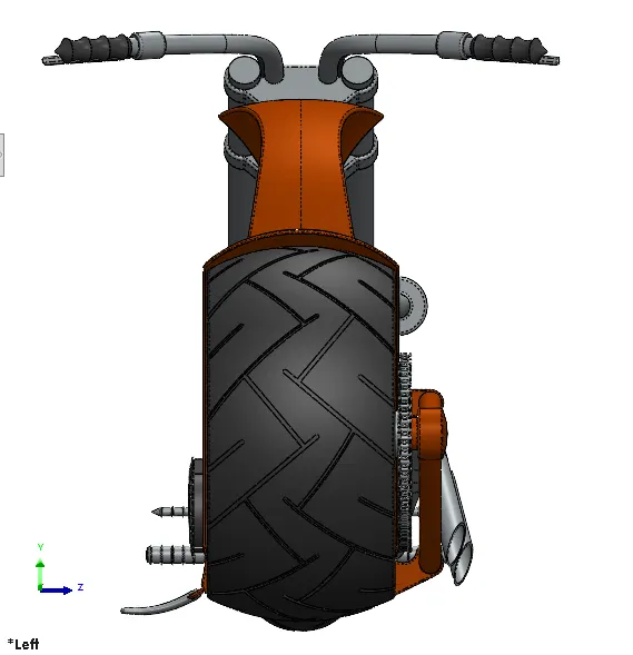
Assembly of American Chopper Bike
After modeling all the parts individually, all the parts are assembled together using appropriate mates.
Following are the different mates which are used for assembly:-
- Coincident Mate
- Distance Mate
- Concentric Mate
- Limit Angle Mate
- Width Mate
- Angle Mate
- Parallel Mate
- Tangent Mate
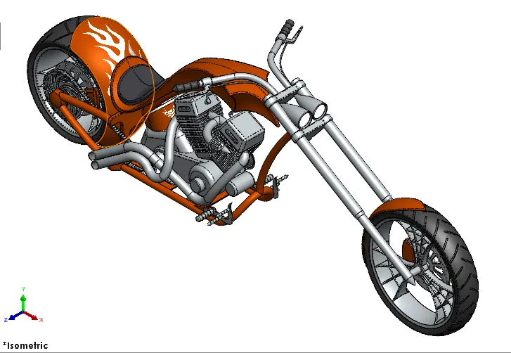
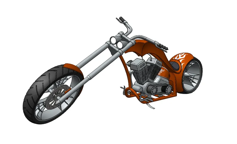
Photorealistic Rendering and Applying Decal
After the complete assembly of the bike, Decals are applied to the individual part on which it is required. Then Appropriate environment and Cameras at different angles are set. Lighting, Brightness, Reflections, and other parameters are also fine-tuned if you are not satisfied with the default settings. When everything is set rendering is done with different environments, colors, and angles.
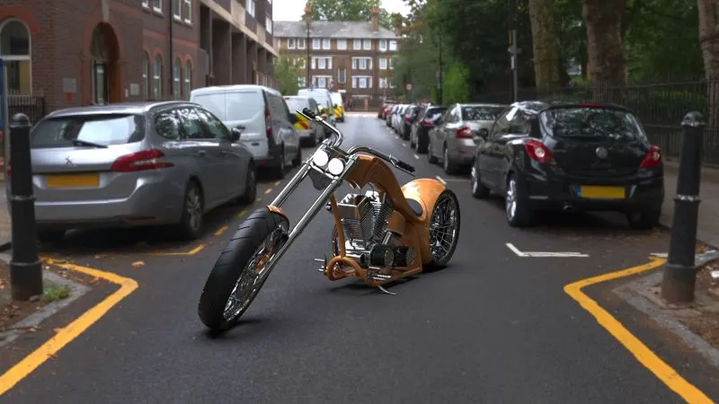
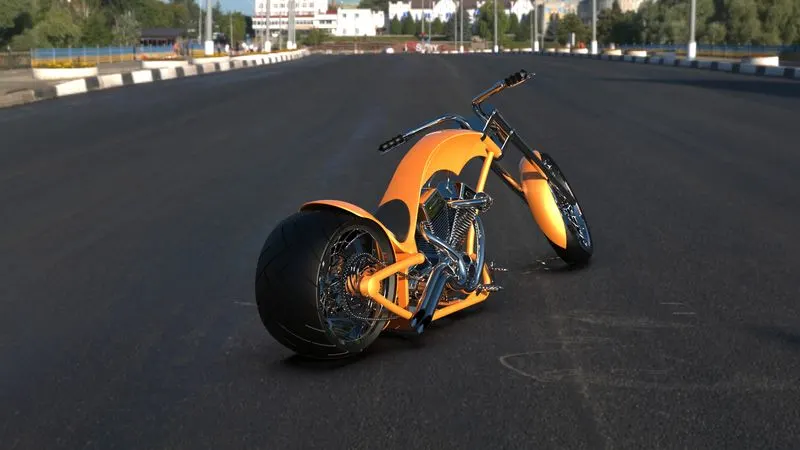
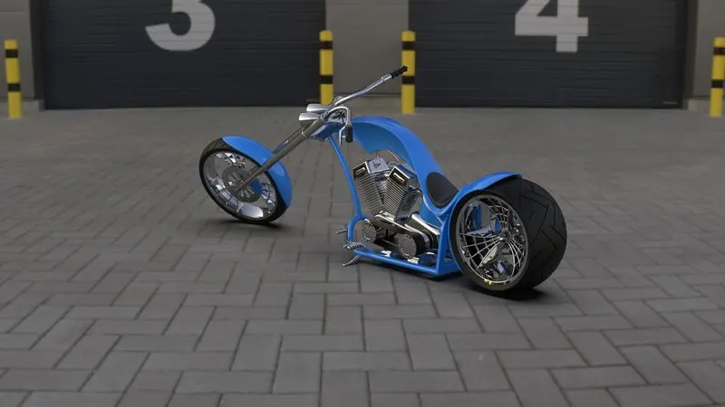
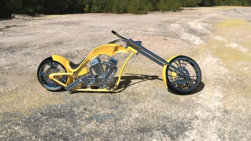
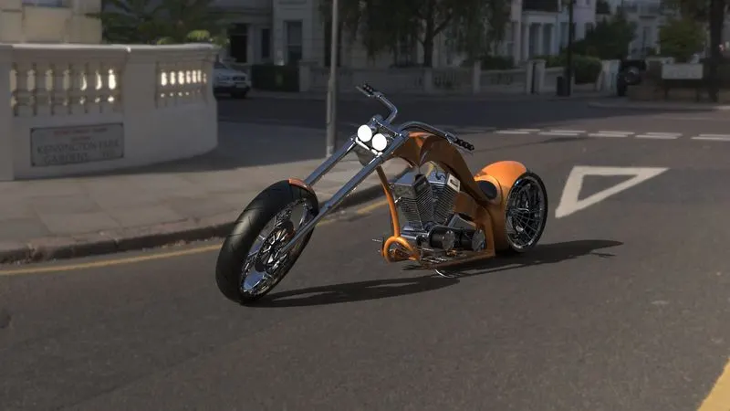
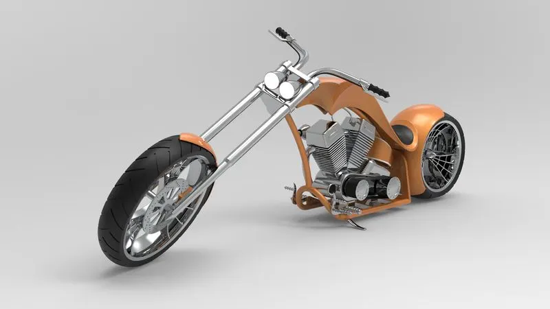
Conclusion: The design of the American Chopper Bike helped to understand various tools of SOLIDWORKS. We got to learn about Solid Modeling, Surfacing, how to handle splines, and many more other things. We have also learned about various mates used in the assembly of the bike and later render the assembled bike with appropriate Color, Materials, Decals, Environment, Lighting, Camera Setup, etc.
THANK YOU
SPECIAL THANKS TO MAHENDRANATH SIR FOR THEIR GUIDANCE THROUGHOUT THE PROJECT.