Week 8 - Challenge 2 - Base Bracket Design
BASE BRACKET DESIGN AND DRAFT ANALYSIS REPORT
OBJECTIVE: To perform draft analysis to check if the part has the given draft on its all faces, to determine the tooling axis and design component using the class-A surface as a reference.
DRAFT: Draft is a tool used in CATIA to make the faces taper with respect to the tooling axis. Tooling Axis is the direction of mold part ejection.
Why draft is necessary?
When developing parts for plastic injection molding, applying draft (or a taper) to the faces of the part is critical to improving the moldability of your part. Without it, parts run the risk of poor cosmetic finishes and may bend, break, or warp due to molding stresses caused by the plastic cooling.
Draft Ange Recommendations:
- 3° is Nominal Draft.
- 0.5° is a minimum draft which increases the cost of manufacturing.
- 7° for Textured Faces.
Procedure:
Draft analysis:
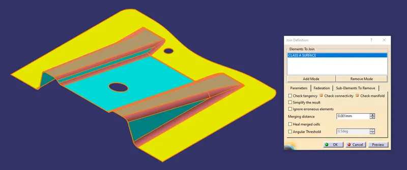
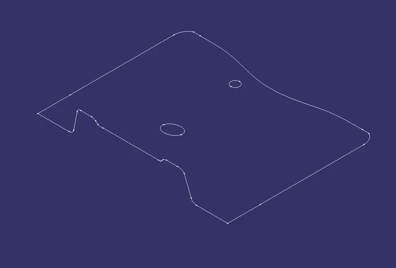
- First, Check the Class A surface that it has no gaps. To check, use JOIN or BOUNDARY command. In JOIN, it will highlight the surfaces individually if there is more than one. In BOUNDARY, it will create a boundary line along all the edges of the surface and after hiding the Class A Surface we can check if there is any unexpected line.
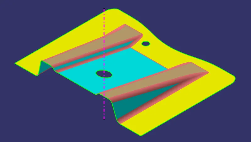
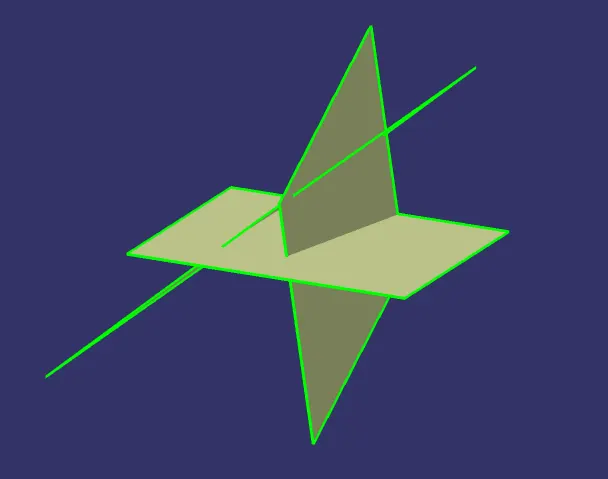
- Now we analyze the best possible Tooling Direction using the X/Y/Z planes. For that, we will create a Dummy Tooling Axis. To create a tooling axis first we extract a point from the boundary line of the hole and then using that line we will create a line along Z-Axis.
- Now we will create a New Plane using the point from which we created the dummy line parallel to the YZ plane. From that plane, we will create an intersection of the surface.
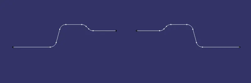
- From the intersection, we will create 2 lines.
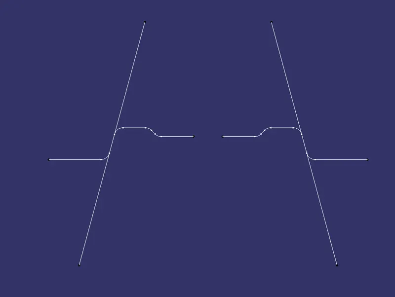
- From the 2 lines, we will create a bisecting line and name it Tooling Clearance X Direction.
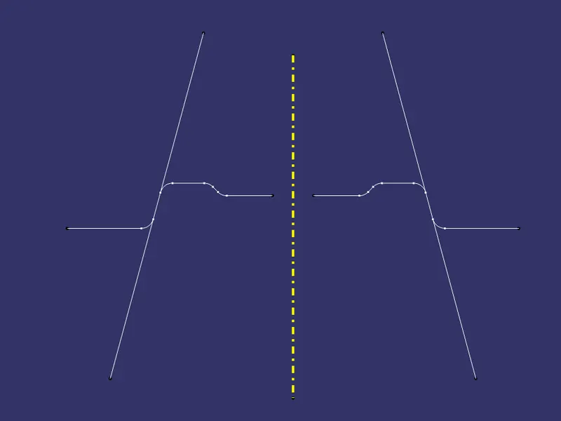
- Using the Tooling Axis we will do Draft Analysis.
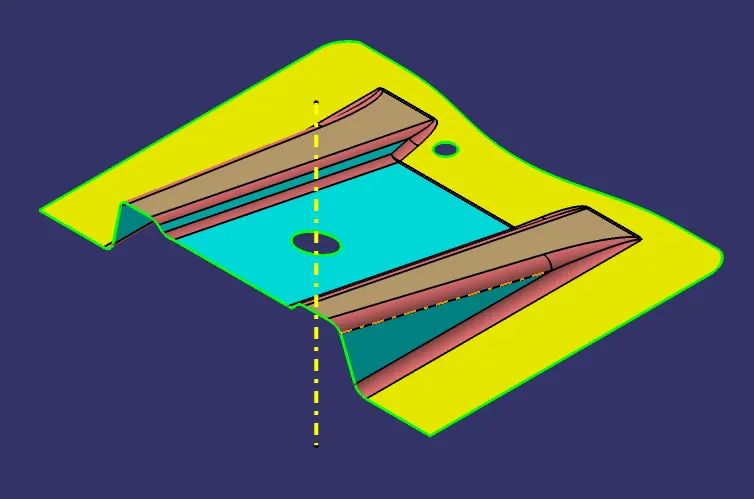
- Go to Insert>Analysis>Feature Draft Analysis. Two Dialogue boxes will open.
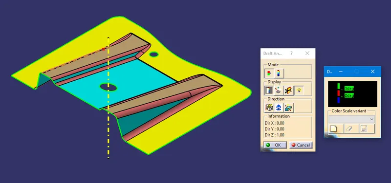
- Under the 'Direction' Tab (Highlighted in Black) select 'uses the compass' option (Highlighted in Red)
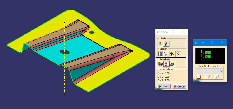
- Place the compass on the tooling axis and lock the direction using the 'Lock or Unlock the draft direction Button on the left side of the 'uses the compass' button.
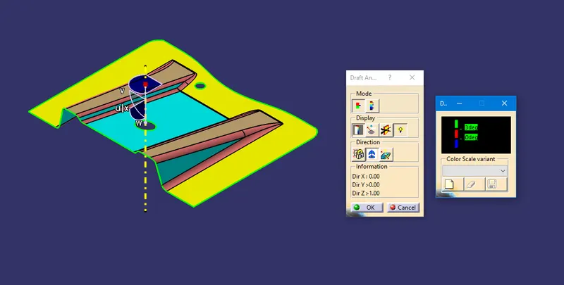
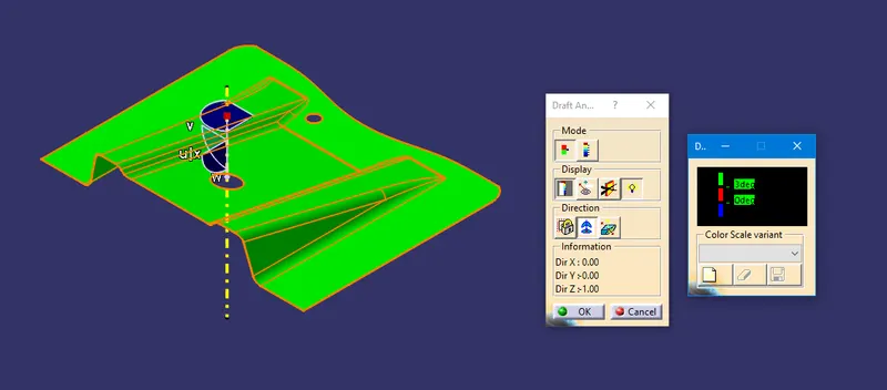
- Now select the surface. Using the dialogue box on the right side you can change the draft value. As the surface is showing green color it is OK for the draft. IF it is not OK for the draft it will show other colors for undercuts and where the draft is required.
Class B Surface:
- Considering the thickness of the component as 2.5mm. Now we have to create a Class B Surface which will be similar to the A Surface at an offset value of 2.5mm.
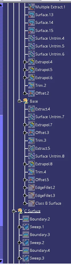
- In this operation first, we create the Ribs. to create ribs we have to extract the surface from the class A surface. For easy understanding of surfaces with will give different group colors to the surfaces.
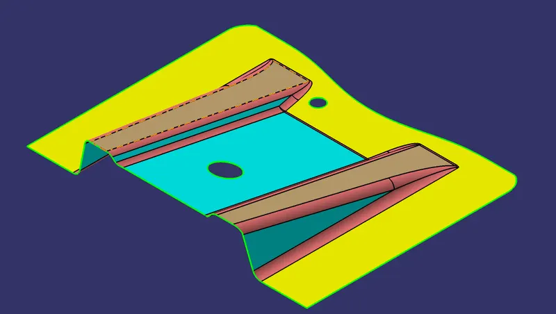
- Extract rib 1 from class A Surface.

- Untrim all surfaces.
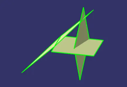
- Extrapolate all surfaces so that they intersect each other properly for easy trimming.
- Trim all surfaces together and create a 2.5mm inward offset of the surface.
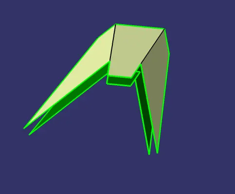
- Do the same steps for Ribs 2 Extract from class A, Untrim, Extrapolate, and then offset.
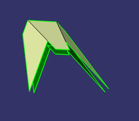
- Do the same process for remaining surfaces as well Extract from class A, Untrim, Extrapolate, and then offset.
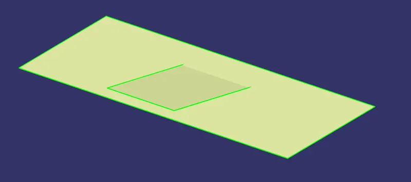
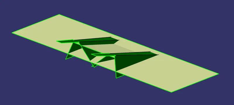
- Now trim all the surfaces together and apply fillets were required with respect to the thickness. This is our class B Surface.
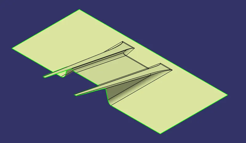
Class C Surface
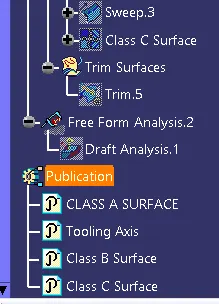
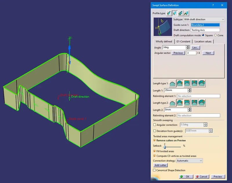
- To create a Class C Surface, First, extract the boundary of the Class A Surface.

- Using the sweep command sweep the profile along the Tooling Axis with Draft. Go to the Toolbar>Sweep>Profile Type>Line>Subtype>With Draft Direction. Select the boundary as Guide CUreve 1 and Tooling Axis for Draft Direction. Also, select the desired draft direction using the 4 arrows.
- Do the same process for holes.
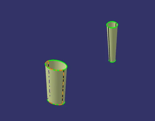
- Join Class A and Class C Surfaces Together.
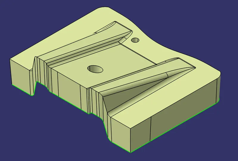
- Trim this surface with Class B Surface.
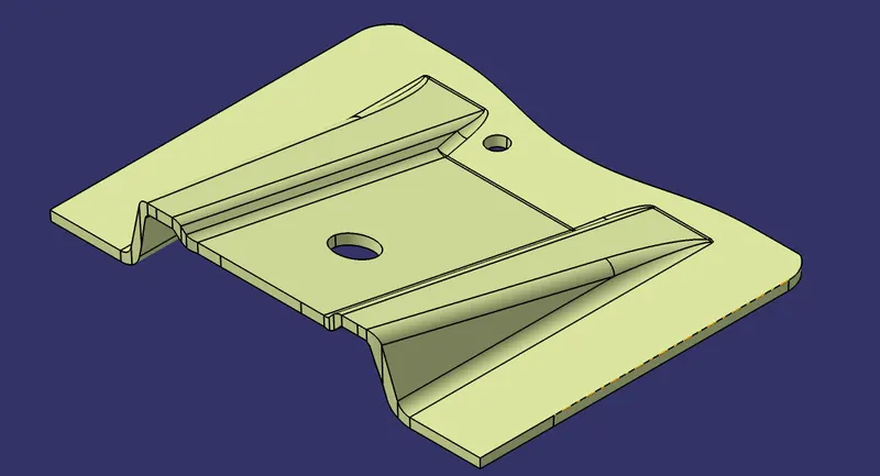
- Using the Close Surface command from Part Workbench form a Solid Body from Surface Body.
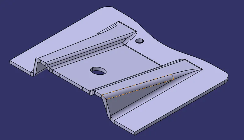
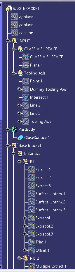
- For easy access to the Class A, Class B, Class C Surface, and Tooling Axis use publish command. It will publish all of the at the end of the tree as shown in the tree.
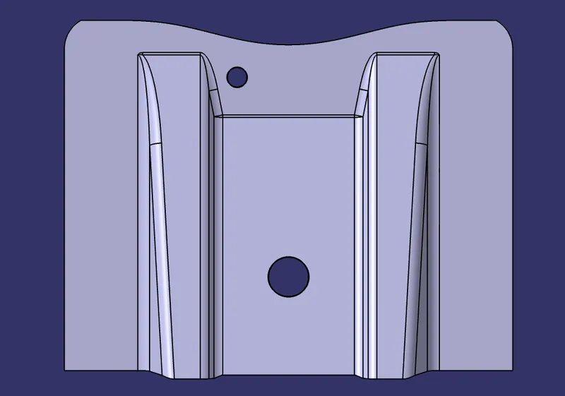
Front View
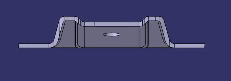
Top View
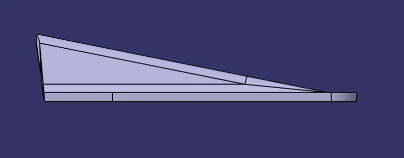
Side View
Tree