Wiring harness routing & packaging Rules Week 3 Challenge
1] Defining the p clamp as electric support using electric part design workbench
- First download the P clamp cad file and open it in CATIA V5.
- Next in part design create points and planes at the centre, two points and two planes at the entry point and exit point. And one plane 2mm offset from the surface where the wires will pass from.
- This is how we define the geometric parameters for the P clamp.
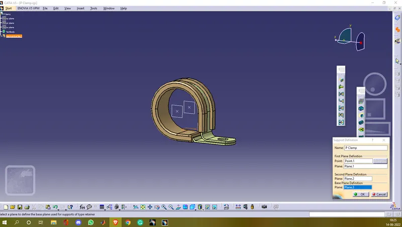
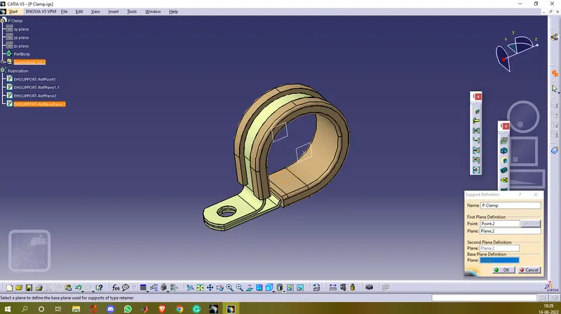
- Now in electric part design we define the P clamp as a support part.
- In first plane definition we select point as point.1 and plane as plane.1 and consider it as the entry side for the wires and in second plane definition we select plane as plane.2 and in base plane definition we select plane as plane.3.
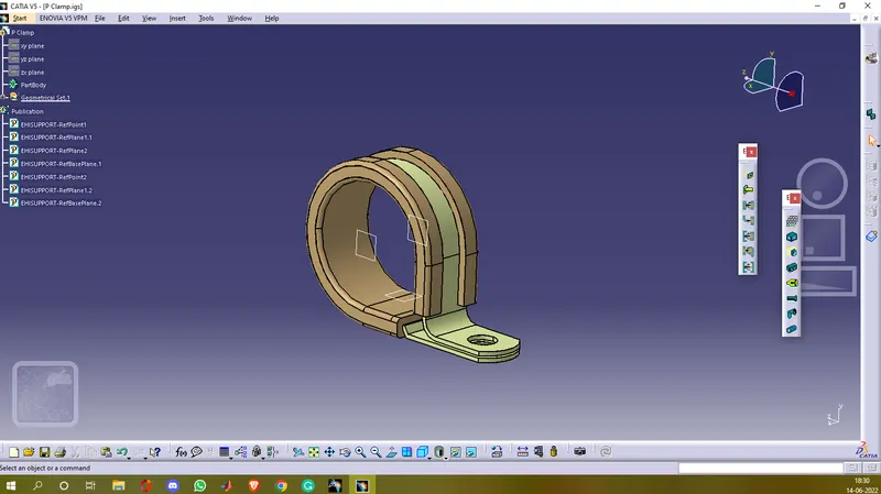
- We repeated the same process for the exit side just replace point.1 and plane.1 with point.2 and plane.2 respectively.
- Now the P clamp is defined as an electric support part.
% Screenshots
2] Defining the back shell as an electrical back shell using Electrical Part design Workbench.
- First download and extract the cad file.
- Now in part design add an axis on the back shell connection surface and a point on the bundle connection side.
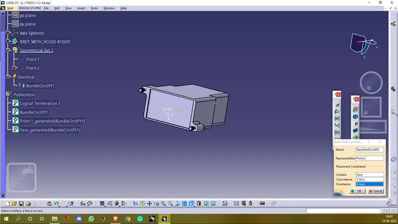
- Next in electrical part design define bundle connection point and define back shell connection point.
- While defining the back shell connection point take the origin point of axis as representation and select contact as the face (surface on which the origin point is) and select y-axis as coincident and x-axis as orientation.
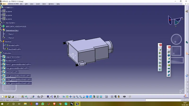
- Now the back shell is defined as an electrical back shell.
% Screenshots
3] Creating corrugated tubes and adding them in a catalogue under 'SlitCOT' family
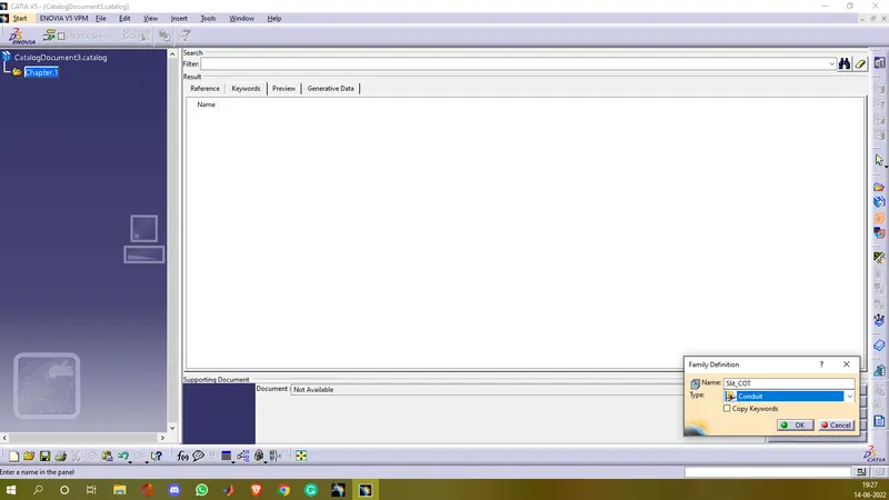
- First we create a catalogue by clicking on file>New part>Catalogue document.
- Next clicking on add family we can name the catalogue and select type as conduit. After saving that catalogue on the computer. We will use this catalogue later in this process.
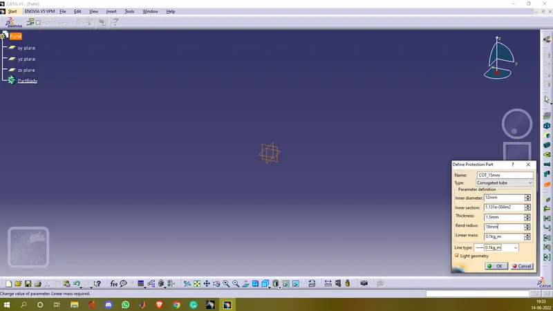
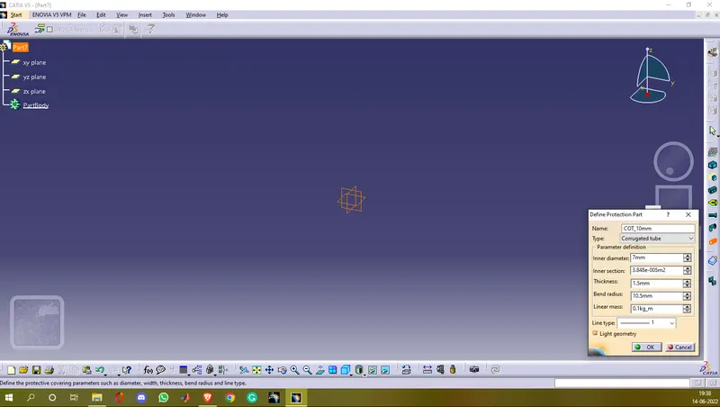
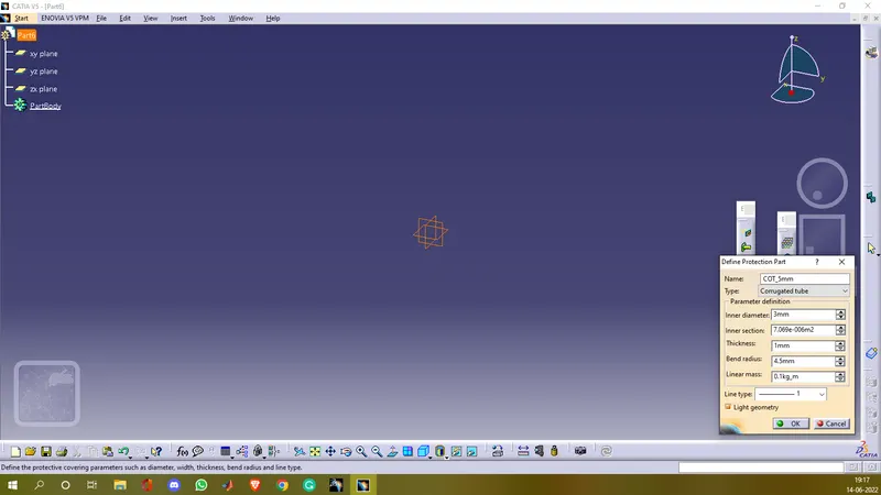
- Now in electric part design we define protection part and input the name for the first corrugated tube i.e COT_15mm and input the inner diameter i.e 12mm thickness 1.5mm and since the bend radius is 1.5 times the inner diameter we take 18mm as bend radius.
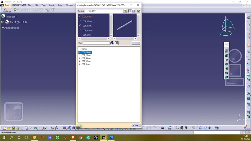
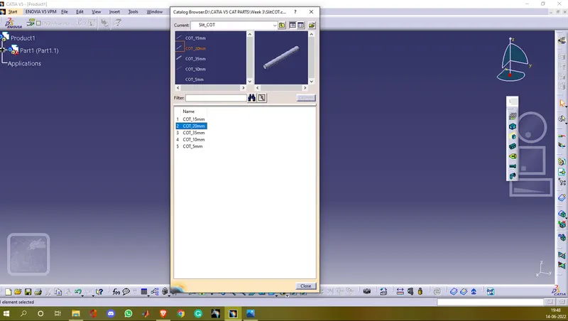
- Now the corrugated tube of 15mm diameter is created. After saving the cad file on the computer we add the COT_15mm to the Slit_COT family catalogue by selecting storage device option.
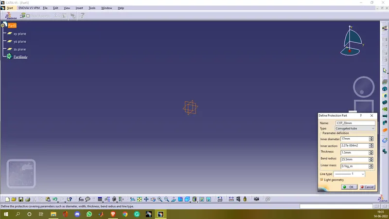
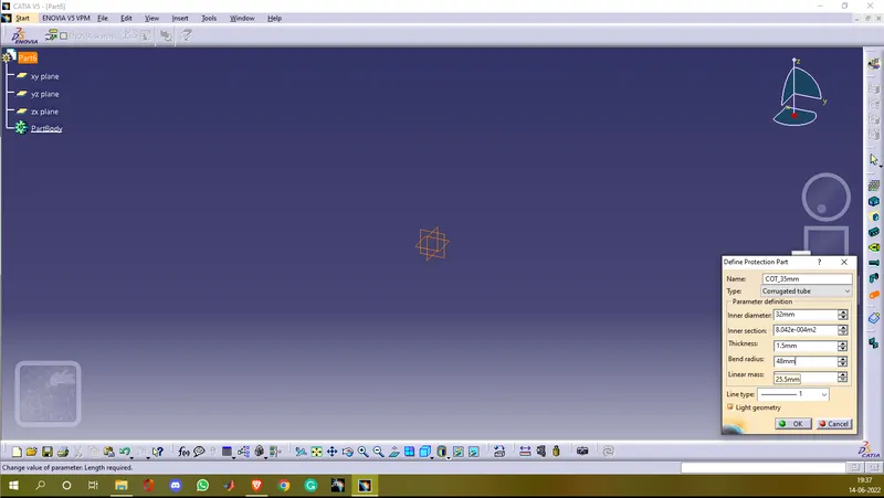
- After repeating the same process four more times with the given values in the challenge we create and add all the corrugated tubes to the Slit_COT family catalogue.
% Screenshots
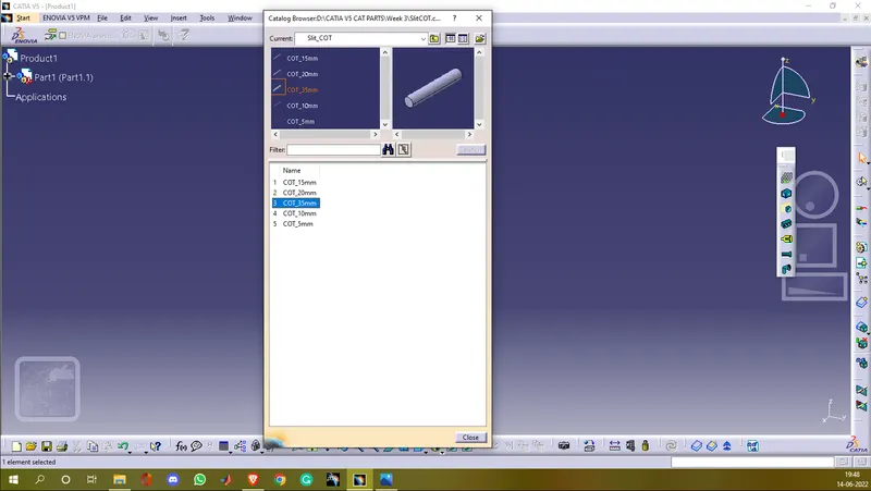
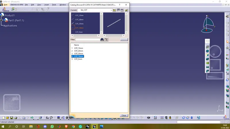
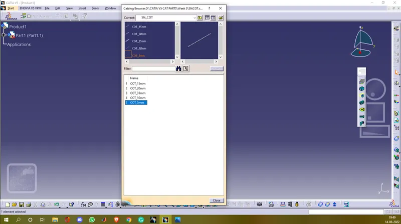
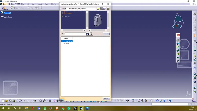
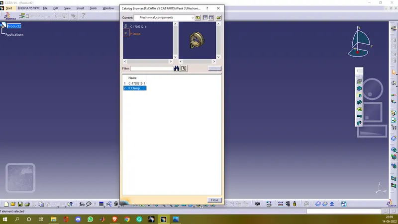
% Creating catalogue for the mechanical components (P clamp and back shell)
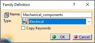
- To create a catalogue the process is the same as creating a catalogue for the corrugated tubes here instead of selecting conduit type we have to select the electrical type. The rest process is the same.