Wiring harness routing & packaging Rules Week 3 Challenge
P-CLAMP
Define Geometry Parameters
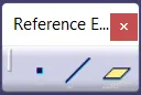
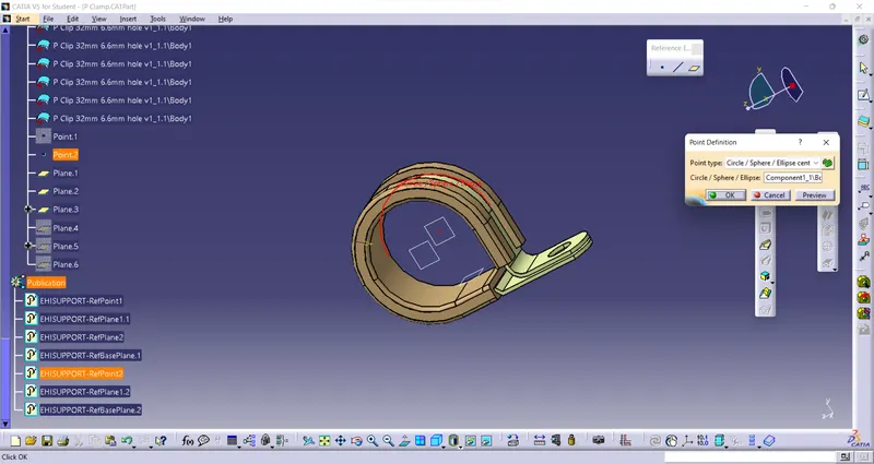
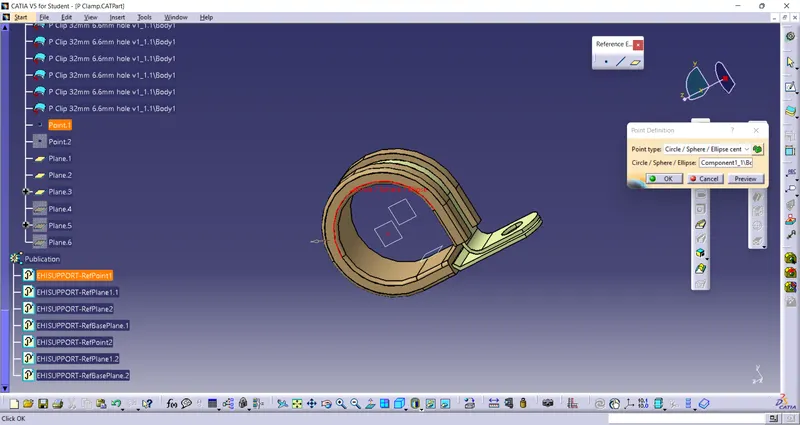
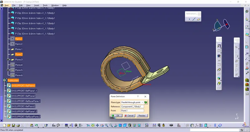
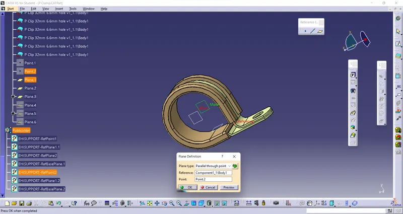
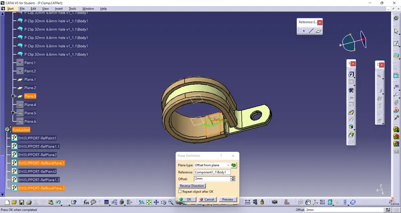
In Mechanical Part Design (MPD) workbench we have to define points and planes for clip using following tools
Points - 2 points at entry and exit
Planes - 2 for entry & exit, and 1 base plane
Define Part As Support
In Electrical Part Design (EPD), choose Define Support Part tool to convert mechanical clip into electrical support clip/part

Define Entry Plane and Point
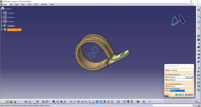
Define Exit Plane and Point
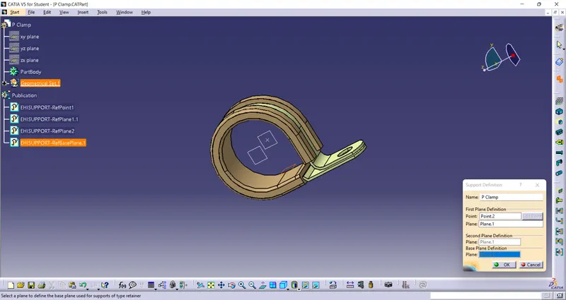
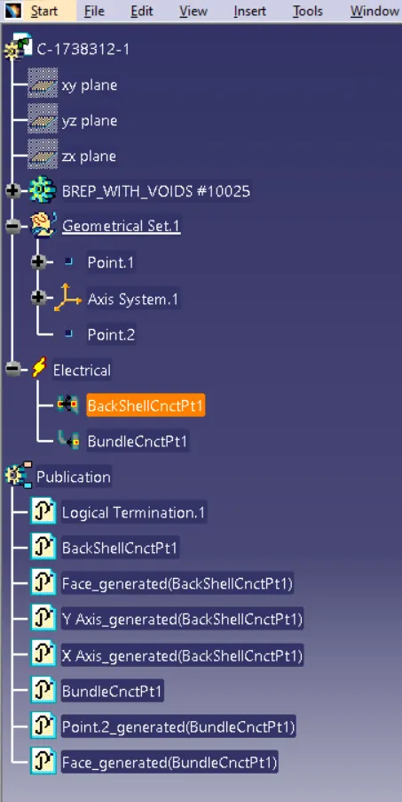
Tree
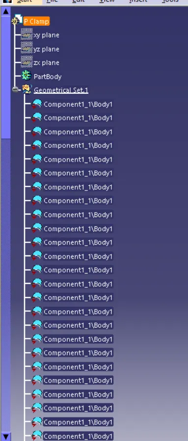
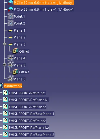
Backshell
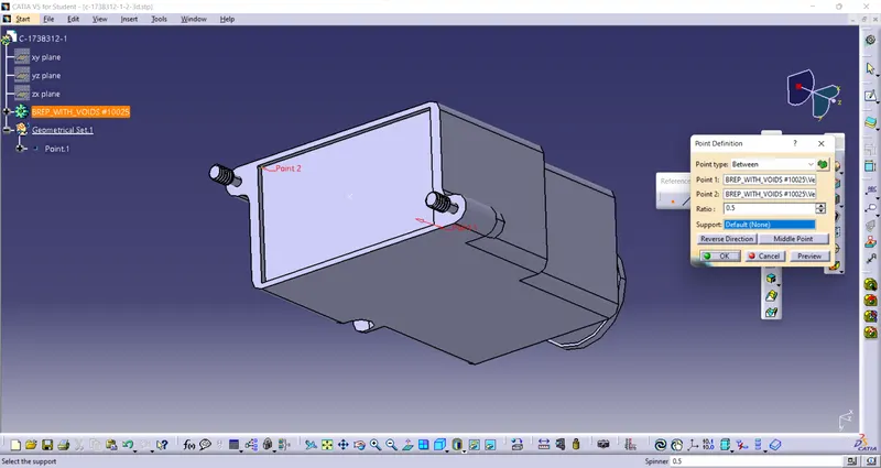
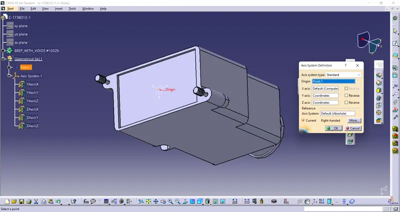
Creating Geometrical Parameters (Axis & Points)
Points & Axis - First we have to load a given file/component in Mechanical Part Design (MPD) workbench. We have to use following tools as shown in fig to define points and axis
(Y-axis - normal to connector front face
X-axis - pointing toward up/down along front face
Z-Axis - along right/left direction).

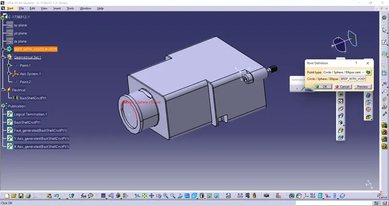
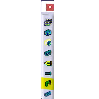
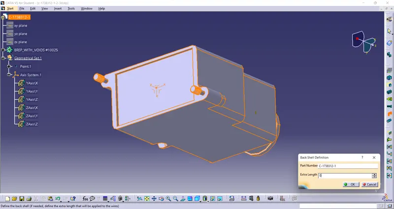
Define Part As A Backshell
We have to convert our mechanical part into Bckshell by using Backshell tool available in Electrical Part Design(EPD) workbench.
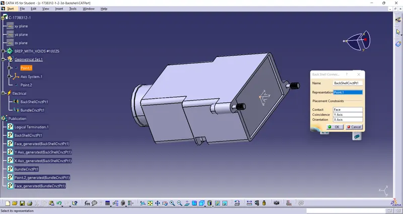
Backshell Connection Point
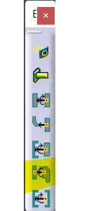
In EPD workbench we have to select Bundle Connection Point tool to define bundlle connection point.
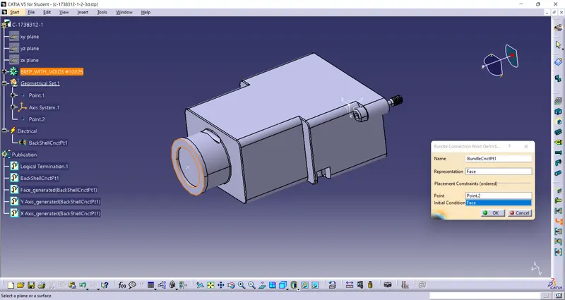
Define Bundle Connection Point
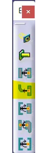
In EPD workbench we have to select Bundle Connection Point tool to define bundlle connection point.
Tree
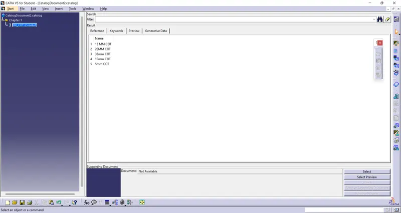
CATALOGUE
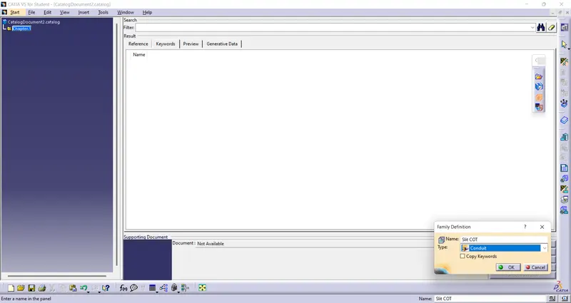
Create a Catalogue
New > CatalogueDocument > Add Family > Rename it to Slit COT > select Type as a CONDUIT for corrugated tubes/tapes > Save
 .
.
Adding Parts to Catalogue
New > Part > Define Protection Part > select/tap on PART in tree > provide required dimensions > Save > Click on Store Device > Select required Catalogue folder and family > OK