Wiring harness design in CATIA V5 - 3D modeling Week 2 Challenge
Creating Geometrical Parameters (Axis & Points)
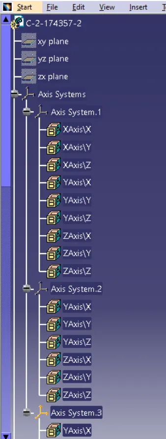
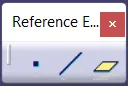
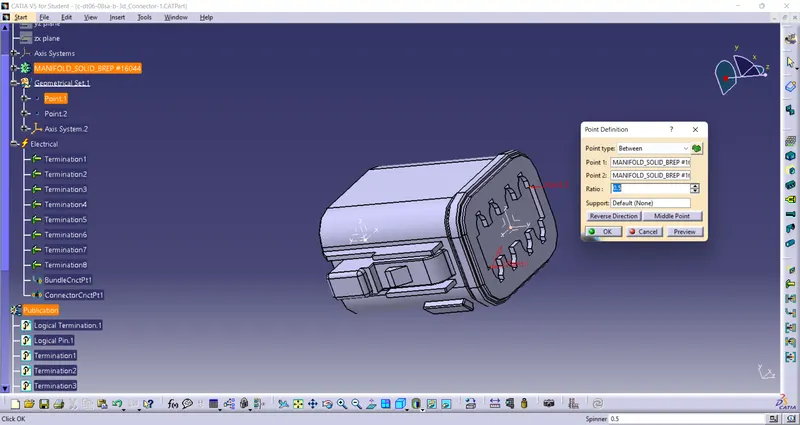
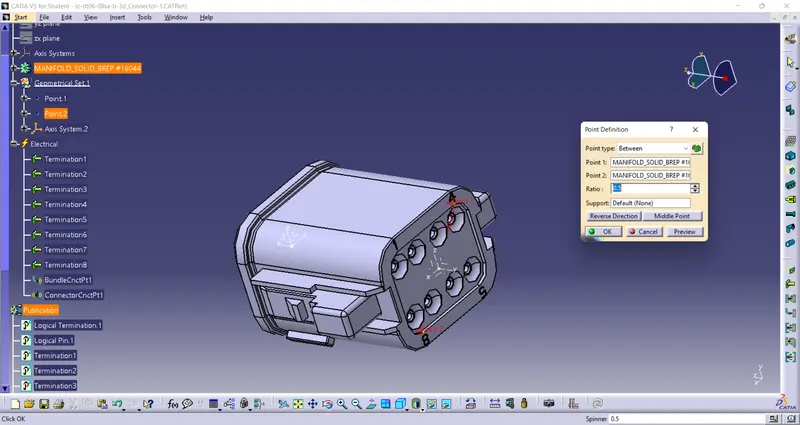
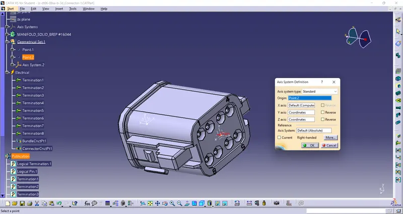
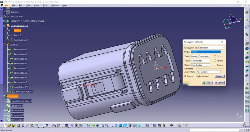
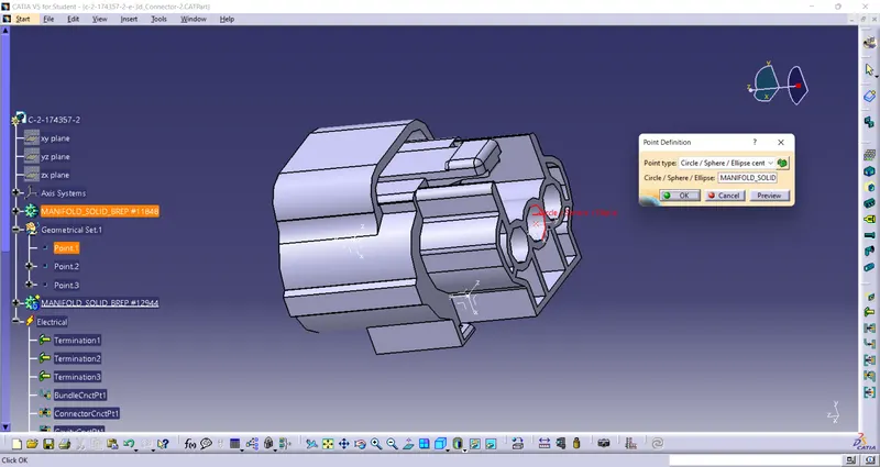
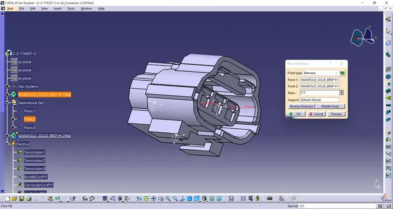
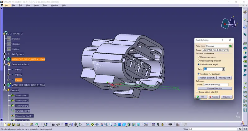
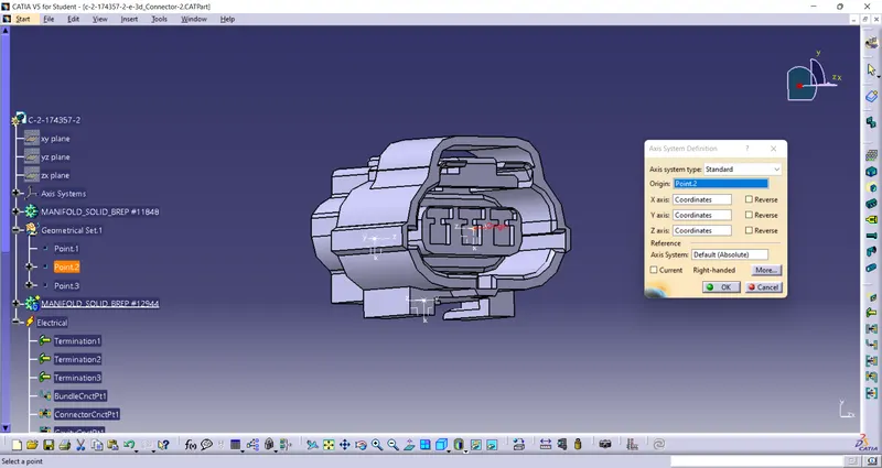
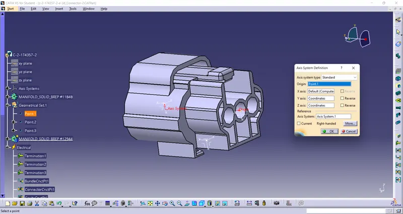
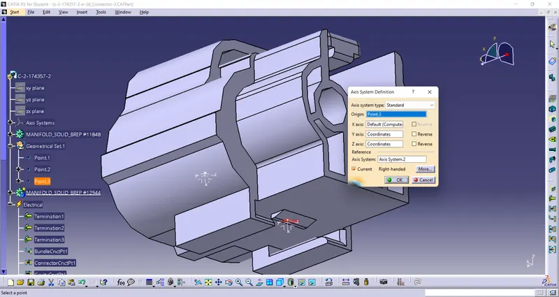
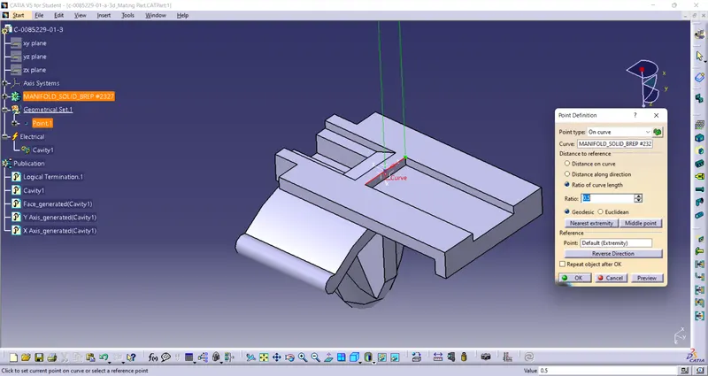
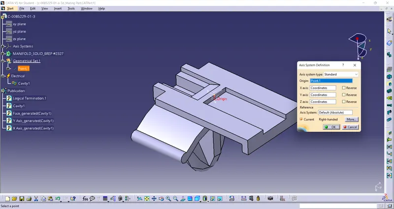
Points & Axis - First we have to load a given file/component in Mechanical Part Design (MPD) workbench. We have to use following tools as shown in fig to define points and axis
(Y-axis - normal to connector front face
X-axis - ponting toward locking mechanism
Z-Axis - along right/left direction).

Define Part As A Connector
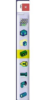
We have to convert our mechanical part into electrical equipmen/connector by using CONNECTOR tool available in Electrical Part Design(EPD) workbench.
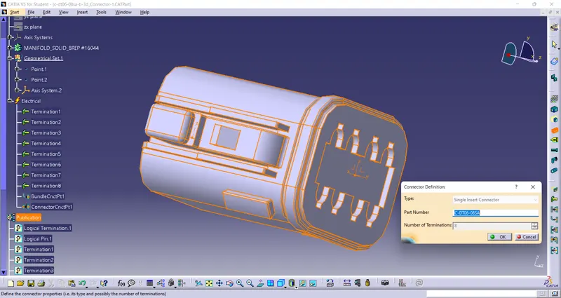
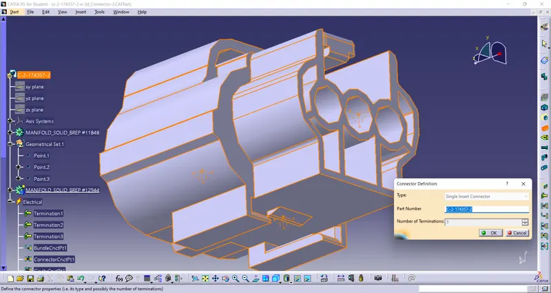
Define Bundle Connection Point
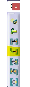
In EPD workbench we have to select Bundle Connection Point tool to define bundlle connection point.
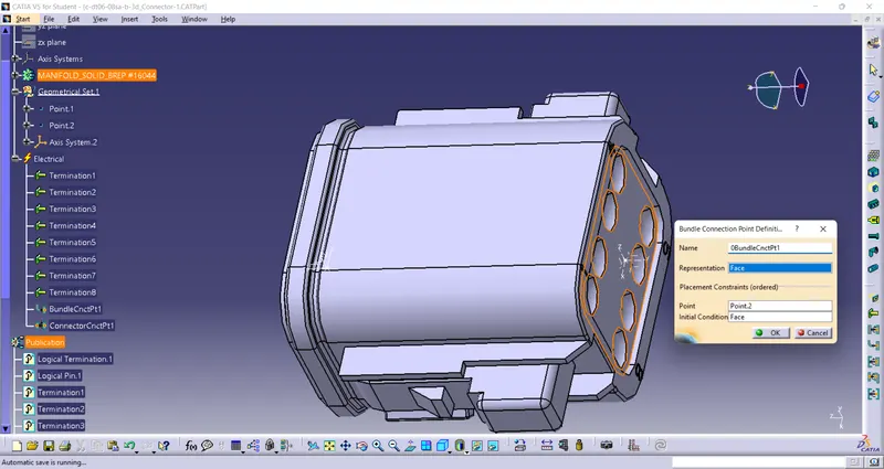
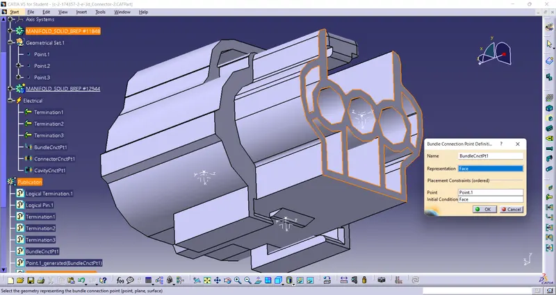
Define Connector Connection Point
In EPD workbench we have to select Connector Connection Point tool to define bundlle connection point.
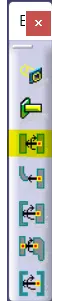
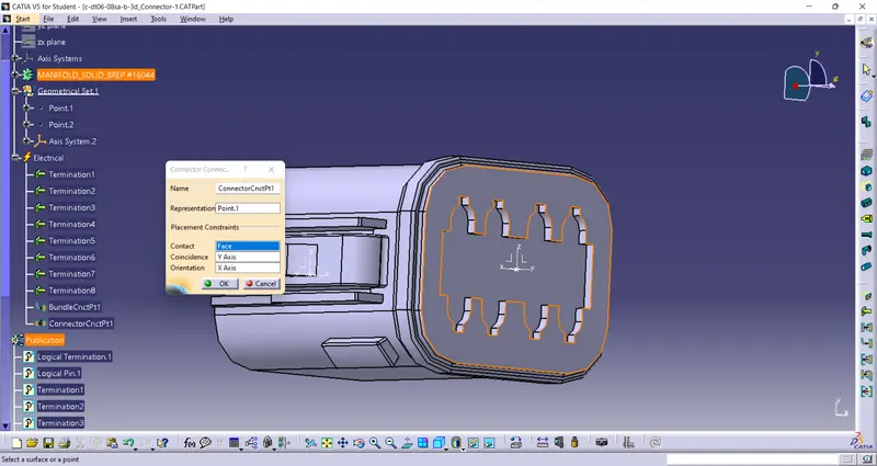
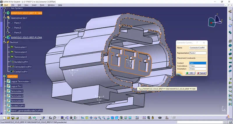
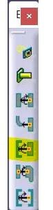
Define Cavity Connection Point (optional)
This step is valid/applicable only for a connector which has connector locking feature.
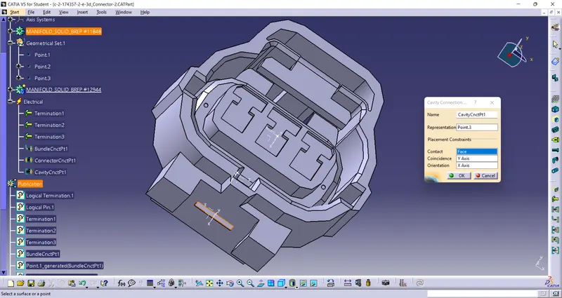
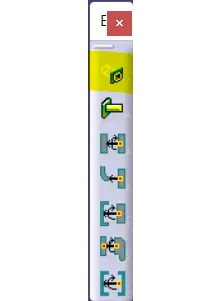
Defining Part As A Connector Cavity/Mounting Clip
After defining axis and point in EPD have to select CAVITY tool to define whole part as CAVITY.
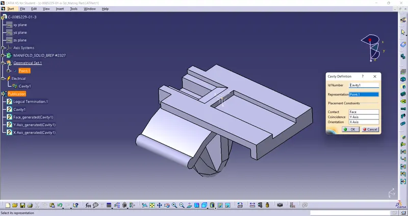
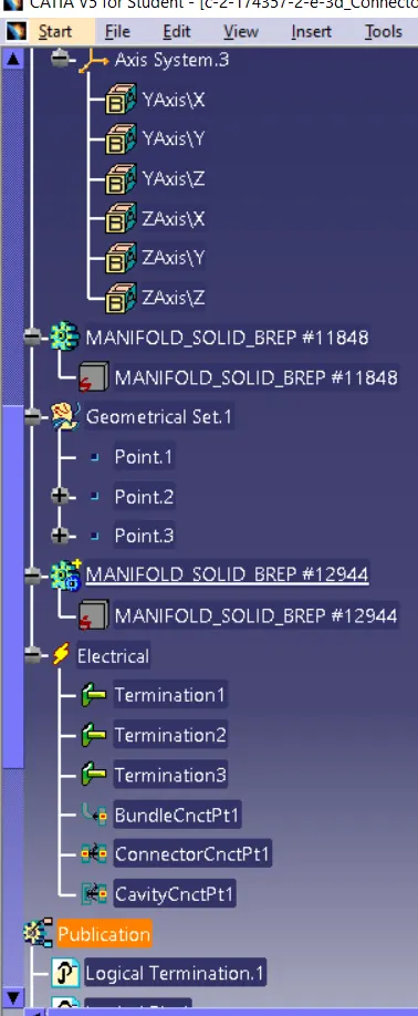
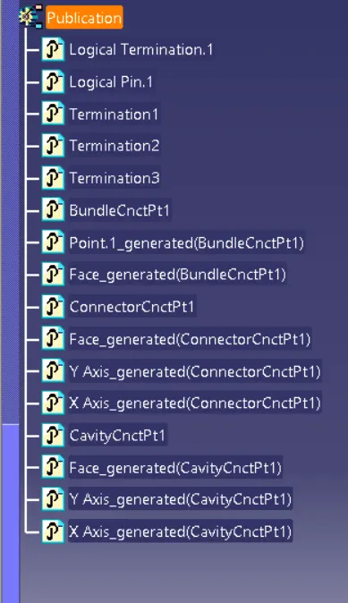
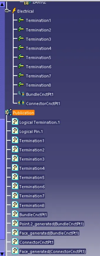
Tree
part 1
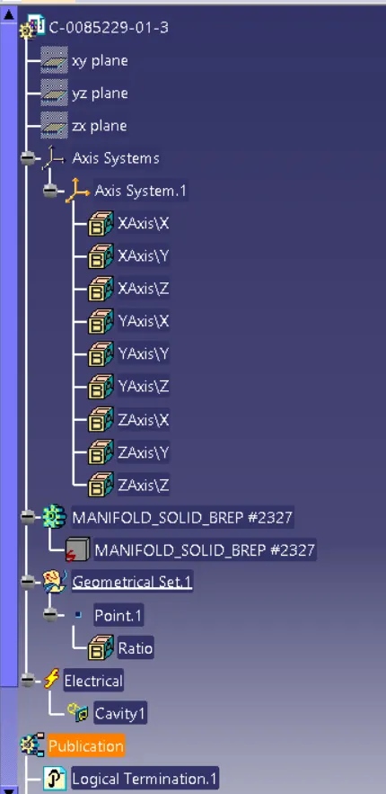
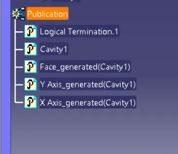
Part 2
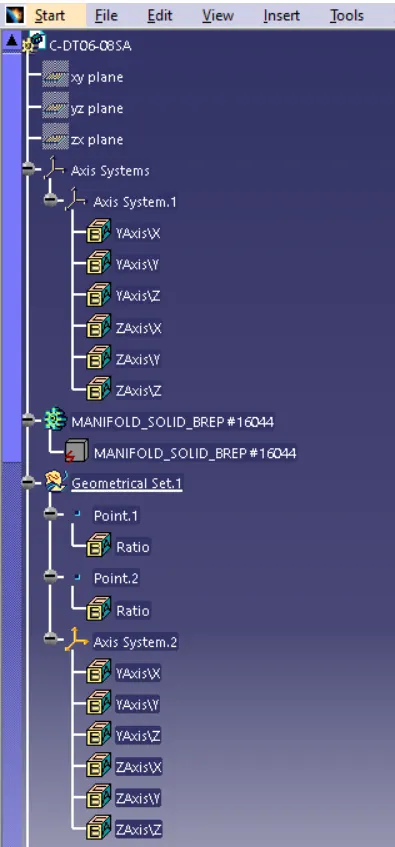
part 3