Wiring harness Flattening:
WIRINING HARNESS FLATTENING:
STEPS FOLLOWED:
New file:
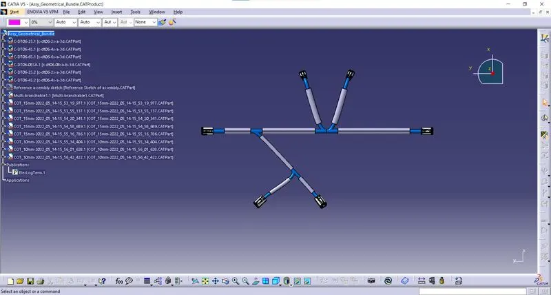
- Open catia V5 and opened a new product file and already created wiring harness assembly routing.
- Rename the product file into a 'Flattening Product file'.
Setting up the flattening parameters:
- Switch to the Electrical Harness Flattening.
- Select the command called Harness Flattening Parameters.
- In general tab, change the minimum angle distance between them to 15 to 20 degree.
- Enable, keep existing tangent between bundle segment and connector during the flattening step.
- Also enable, Extract only the supports inside the geometrical bundle.
- Select the Radius of the bundle segment for the Roll radius for Quick roll.
- Keep the parameters default or change according to our requirement.
- Save this file as a Flattening product in the path where the required wiring harness assembly file is located.
Extract:
- Opened the wiring harness assembly file and tile the window vertically.
- Select the Flattening product file in model tree and select the extract command in Electrical Harness Flattening workbench and select the wiring harness assembly file to fetch the required information.
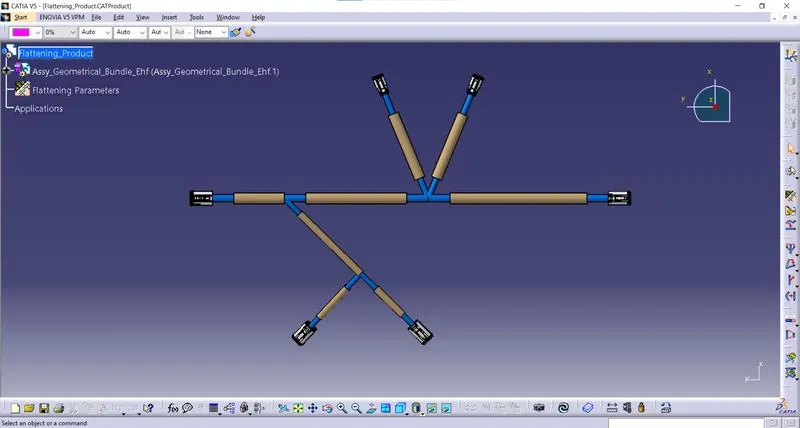
- Now the wiring harness assembly file details are extracted into the flattening product.
- Now select the Flatten command in Eletrical Harness Flattening Workbench.
- Select the active plane as a required surface or any other required planes.
- Keep default parameters in Algorithm mode and Angle mode.
- Select the branches and select ok to perform the Flatten operation.
- Use the other commands such as rotate, roll, straighten and synchronization for the alignment of Flattening product.
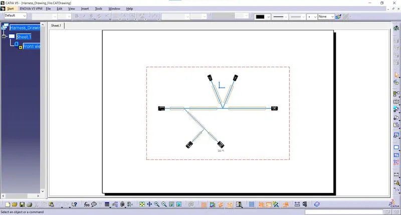
Creating 2D Harness Flattening Drawing File.
- Open the new drawing file and save as a Harness Drawing File.
- Keep ISO as a standard and A0 ISO as a sheet style.
- And select Landscape.
- Now select the Front view command in Drawing file and select the required surface or the plane for view in the flattening product file.
- Now the flatten product details are delivered into the drawing file in a 2D.
- Now go to the properties and select the view tab, under dress up section, enable the 3D colors (if needed) and also enable the 3D wireframe is always visible.
- Now the full details of flatten product details are obtained in a 2D form.
- Now the connectors are represented in a 2D. So we can change the representation into 3D by changing the flattening parameters in the flattening prodct file.
WIRING HARNESS ROUTING ASSEMBLY:
WIRING HARNESS FLATTENING PRODUCT:
2D WIRING HARNESS FILE: