Wiring harness design in CATIA V5 - 3D modeling Week 7 Challenge
Wiring harness design in CATIA V5 - 3D modeling Week 7 Challenge
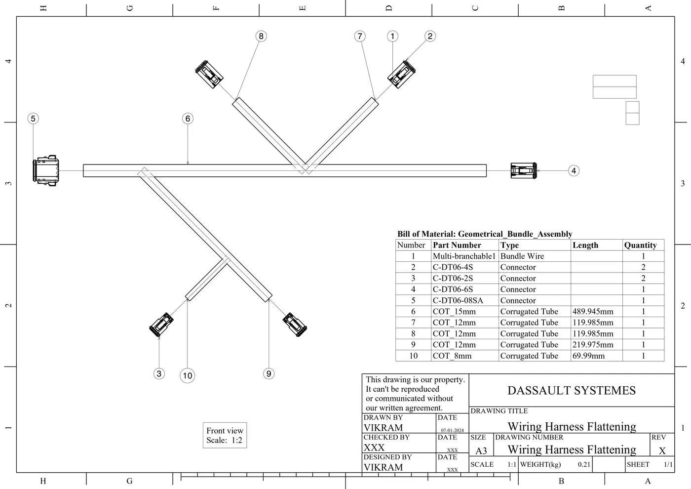
OBJECTIVE: To flatten the wire harness assembly completed in the week 4 assignment and place the flattened view on a drawing sheet. Also, ensure that the bundles with protective coverings have different visuals on the drawing view.
GIVEN DATA:
Wiring Harness Layout:
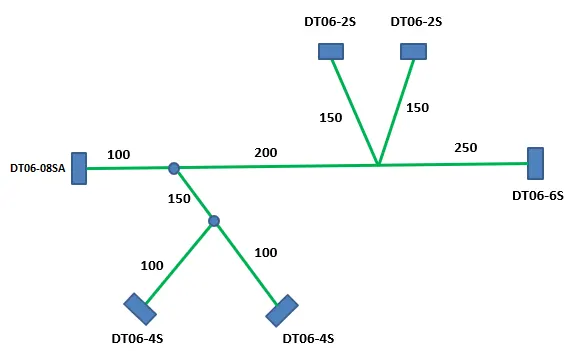
MAIN PROJECT:
STEP-1: Create a new product file, go to the Electrical Harness Flattening Workbench and save the file as Wiring Harness Flattening in the same location where the Geometrical Bundle Assembly is stored.
STEP-2: Define the 'Harness flattening parameters' settings to flatten the required wiring harness assembly as shown below.
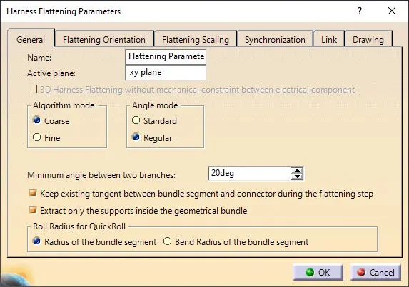
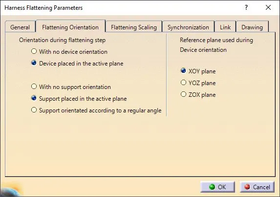
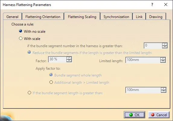
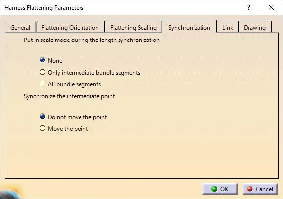
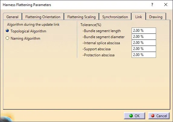
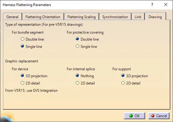
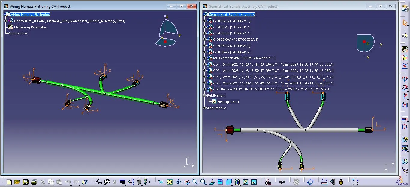
STEP-3: Open both the Flatten Assembly and the Bundle Assembly side by side. Select the 'Extract' option in the Electrical Harness Flattening Workbench and select the Geometric Bundle Product in the wire harness assembly product file. Then Geometric Bundle Assembly is imported to the Wire Harness Flattening product file with an 'EHF' extension.
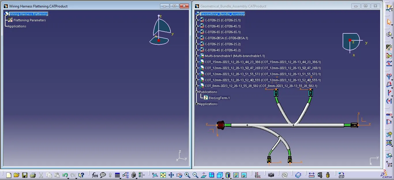
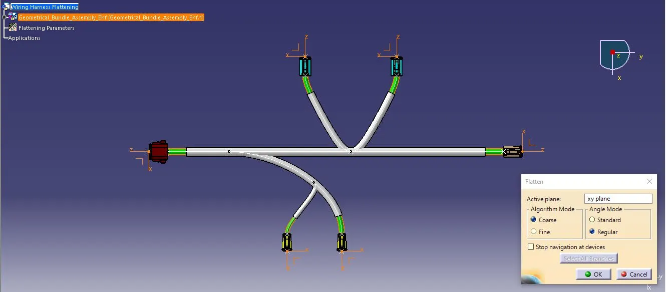
STEP-4: Select the Flatten option, provide the active plane and define the algorithm and angle mode. Then choose the branches which are to be flattened and hit the ok button.
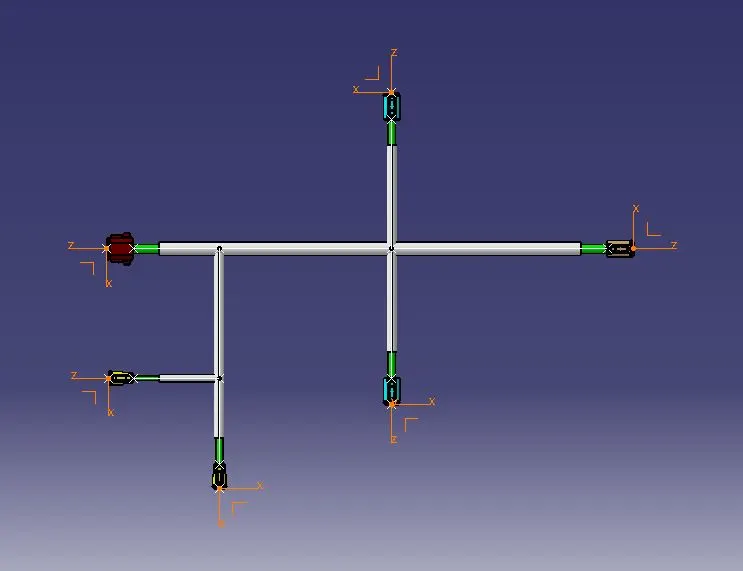
STEP-5: Use 'Rotate' and other commands to align the branches and bring them in proper orientation as per the given layout.
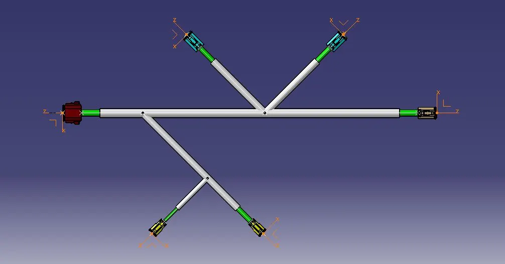
STEP-6: Drawing View
1) Create a new drawing file and ensure to save it in the same designated location. Insert the title block template into the drawing sheet and enter the necessary details within the title block.
2) Insert the front view of the harness assembly by selecting any flat face of the connector. Adjust the orientation of the wire harness for a better viewing.
3) Access the properties of the view and enable the '3D Wireframe' and 'Is always visible' options. This ensures a clear visualization of wire bundles, connectors, and protective coverings.
4) Label all components utilized in the wire harness assembly through the generate balloons feature and BOM. This step contributes to a well-organized and informative representation of the assembly's parts.
Conclusion:
Thus, the wire harness assembly is flattened and a drawing view with different visual representations for the bundle and protective coverings is created.