Wiring harness design in CATIA V5 - 3D modeling Week 7 Challenge
Electrical Harness Flattening
Harness Flatten: -
First, we have to make harness assembly for make flatten
Given drawing for assembly is
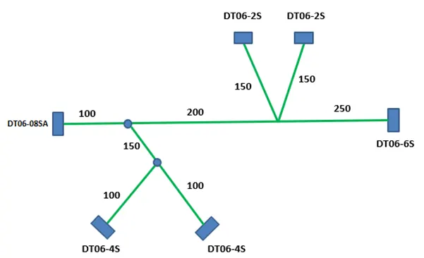
For this assembly we have to download all connectors from TE.com and define them electrically,
Routeing of harness as per given layout in electrical workbench of following connector
- DT06-4S
- DT06-6S
- DT06-2S
- DT06-08SA
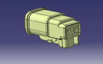
DT06-2S
Defining bundle entry point as we need to route this assembly, we also define connector connection point but here we had no need of connector connection point so we hide it. DT06-2S has two terminals
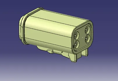
DT06-4S
Defining bundle entry point as we need to route this assembly, we also define connector connection point but here we had no need of connector connection point so we hide it. DT06-4S has 4 terminals
DT06-6S
Defining bundle entry point as we need to route this assembly, we also define connector connection point but here we had no need of connector connection point so we hide it. DT06-6S has 6 terminals
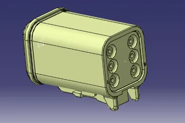
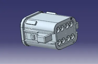
DT06-08SA
Defining bundle entry point as we need to route this assembly, we also define connector connection point but here we had no need of connector connection point so we hide it. DT06-8SA has 8 terminals
After defining all connector electrically, now we have made Geometrical bundle including All connector then we can route this harness
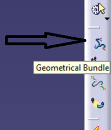
Geometrical bundle
When we set all connector at their places and its time to routeing first, we need to define all connector as geometrical bundle otherwise routing will not work
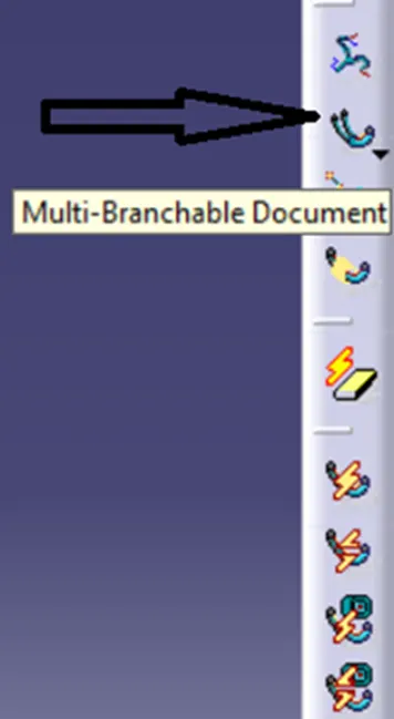
Multi-branchable documents
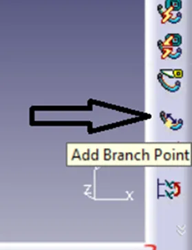
To make connection between two connector or to make sub_branch we use this command
Add branch point
To make sub connection for another connector we use this command
Protective Covering
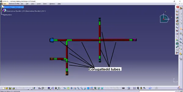
After routeing harness, To Protect wires from cut by mechanical part we need to cover wire by corrugated tubes or cotton tape
We use corrugated tubes Having brown colour
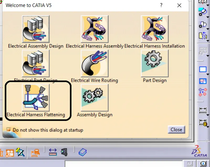
We have to make Electrical Harness Flattening
Using this open Electrical Harness Flattening window
After opening this we can see the window like this
Then to activate flattening we to click on Harness flattening parameter
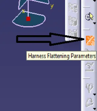
Then in Harness flattening parameter we can change as per our requirements in the parameter box and click on OK
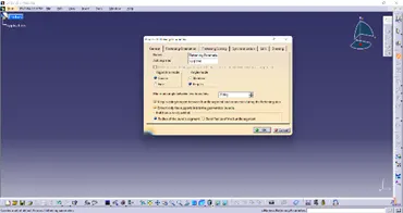
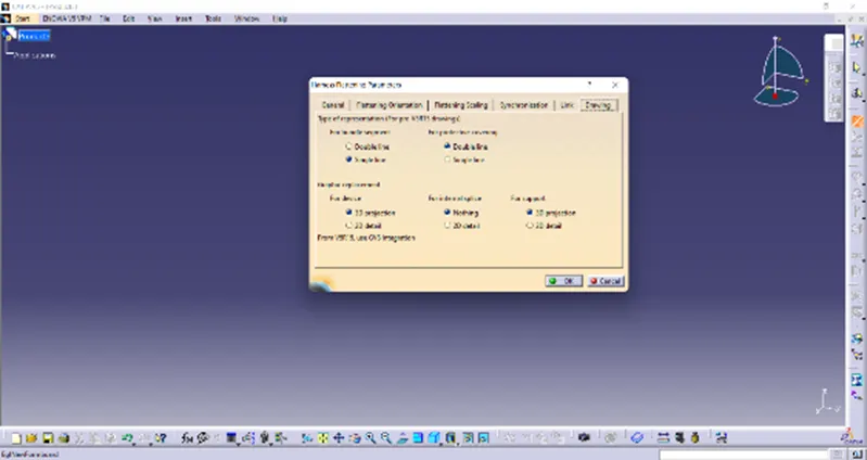
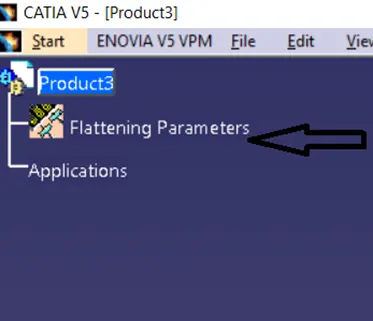
Then we can see Flattening parameter has added
Then to add the bundle we use “extract” command select specific bundle and it will add in flattening
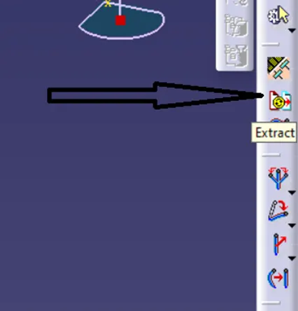
After Flatten bundle we can see harness like this
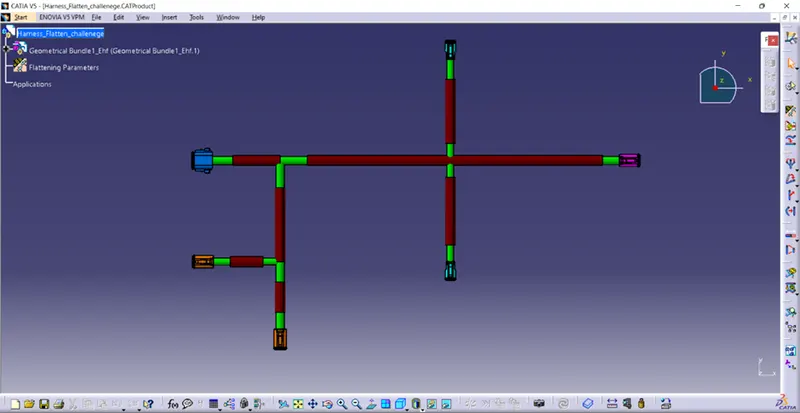
Here all connectors set as all locks of connector looks up sides
We give specific colour to all concoctors and brown colour to corrugated tubes
Then we have made this 3D flatten file in to 2D drawing
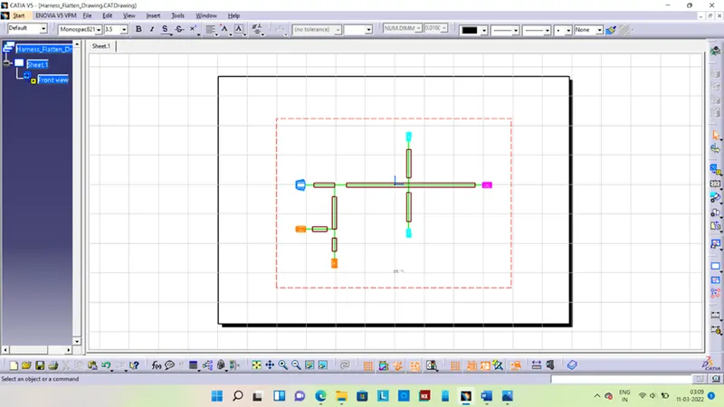
We can see window like this
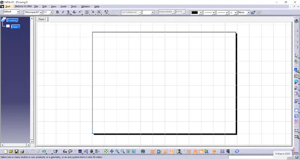
Initially window is blank, we have to add drawing in to it so we have select command Front View then click on 3D part file it will convert 3D file in to 2D files on drawing workbench
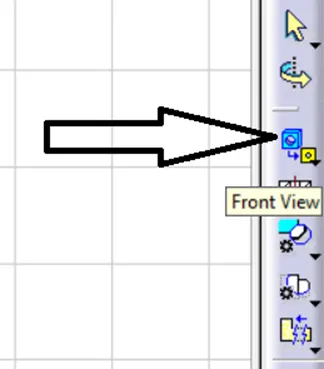
When we convert 3D in to 2D it did not show bundle and colour of connector, corrugated tubes, bundle
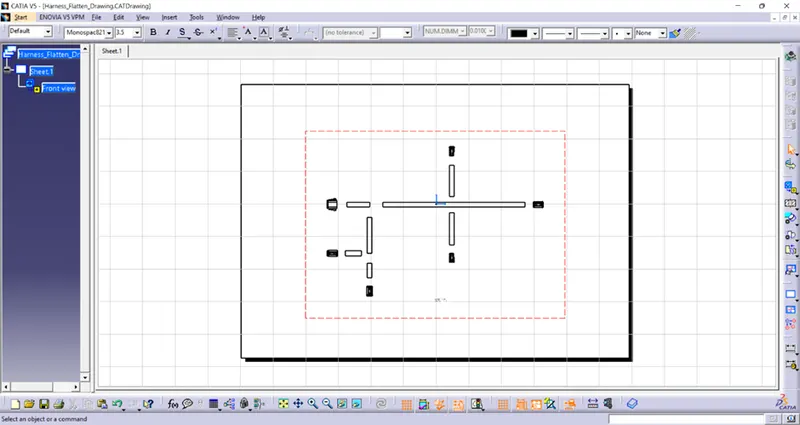
For changes we go to properties of drawing and activate 3D colour and 3D wire frame option
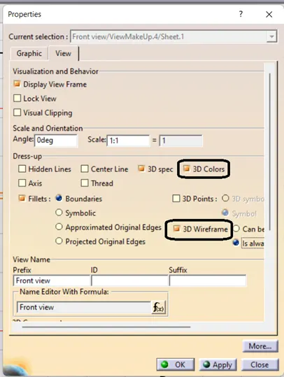
And now colour of all parts and bundle in wireframe showing properly