Wiring harness design in CATIA V5 - 3D modeling Week 7 Challenge
Wiring harness design in CATIA V5 - 3D modeling Week 7 Challenge
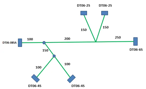
Q1. Flatten the harness assembly completed in “ week 4 challenge”. Place the flattened view on drawing sheet. Ensure bundles with protective coverings has different visuals on drawing view.
ANS:
OBJECTIVE:
Create the flattened view of the previously created harness assembly and then generate its 2D representtion in catia drawing window itself, and assigning different visuals for the protective covering.
INPUT:
HARNESS ASSEMBLY
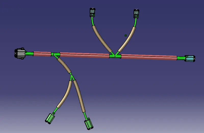
STEPS YOU NEED TO FOLLOW FOR CREATING THE FLATTENED VIEW.
STEP1)Create the product file by the name of the flattening assembly in the flattening workbench and then assign the parameters to it.

STEP2)
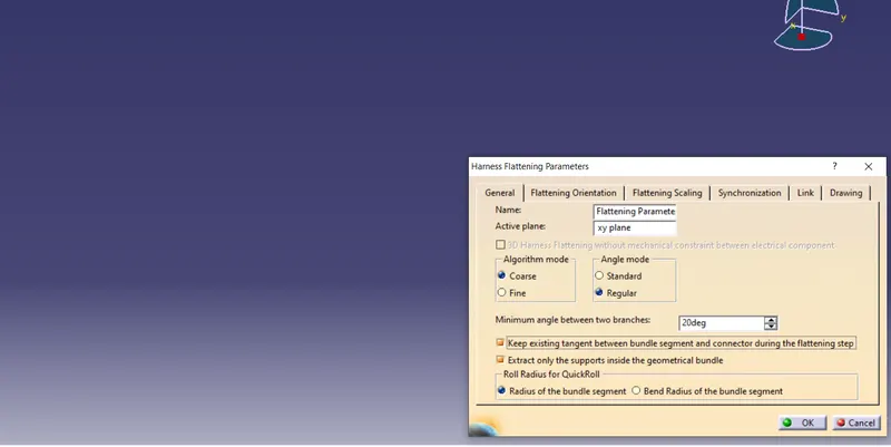
The harness flattening parameter is pivotal step whithout which assembly wont start to work i.e you are not able to deal with any tools available,the parameters are responsible for the orientation i.e the plane , then in drawing section you can select the representation of the devices as 3D or 2D, the parametrs section also enables you to choose between straight and double lines for the cot tubes and routing( using this you can easily distinguish between the assembly parametrs ).
The parameters once defined then you can also change or interpret according to your desire i.e the parametrs can be changed once defined.
STEP3)
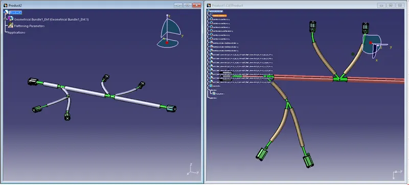
Then you need to add the harness assembly into the flattening assembly by just opening the harness assembly and flattening assembly simultaneously and the using the extract commmand to add to the main flattening assembly.
STEP4)
Next step is using the flatten tool to flatten the assembly, the plane is required for assigning the flattening plane, then the branches need to be selected that need to be flattened.
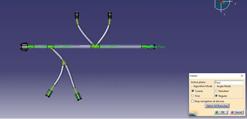
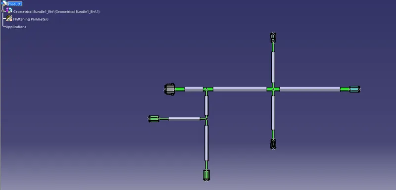
STEP5)
Then use the rotate tool bar to represent the flattened view relative to the harsess assembly(i.e geometrical bundle), the rotating plane would be the one you selected while assigning the flattening parameter ,you can even change if its not orienting properly.
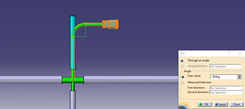
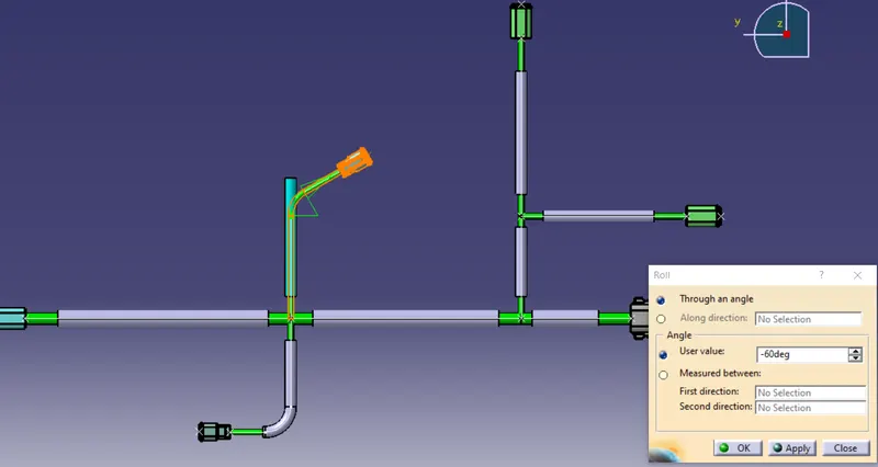
STEP6)
Then make the view more precise by using roll over , roll , blend tools in order to present more professionally.
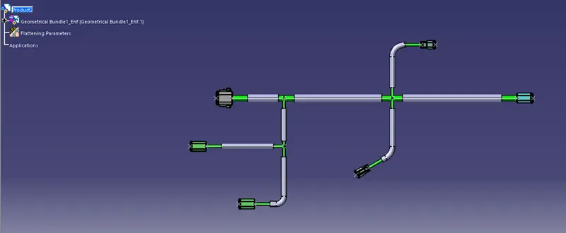
STEP7)Use the drafting workbench for 2D representation of the flattened assembly, the sheet size, views etc need to be slelcted prior to the drafting workbench.
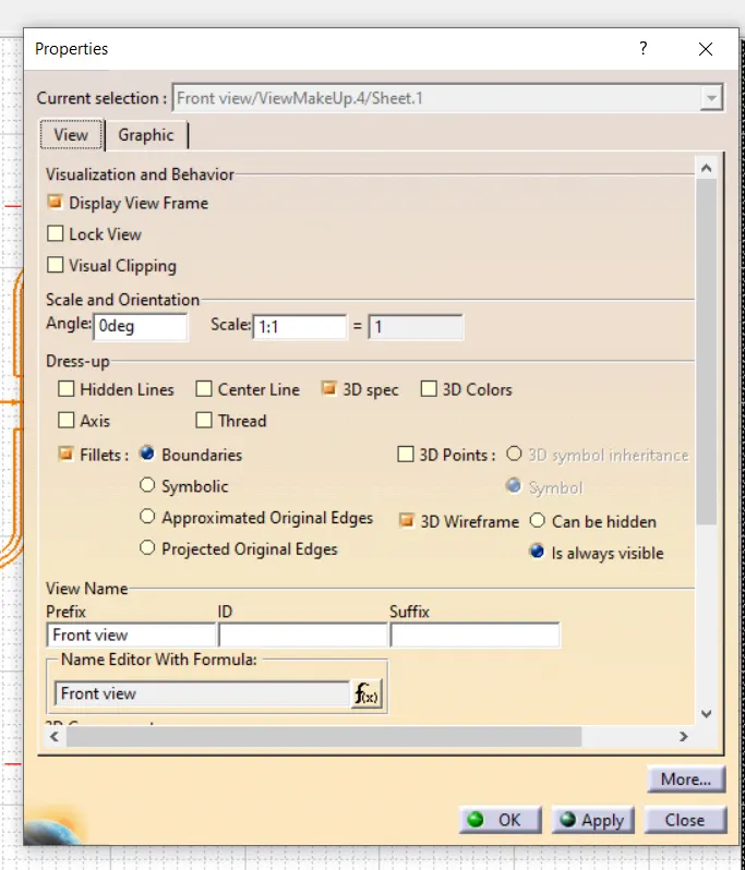
LAST STEP is list the drawing properties make sure that that 3D wireframe is "ON" so that the routing is visible to us.
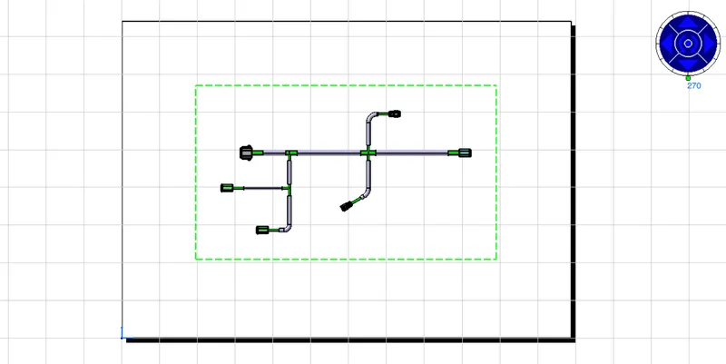
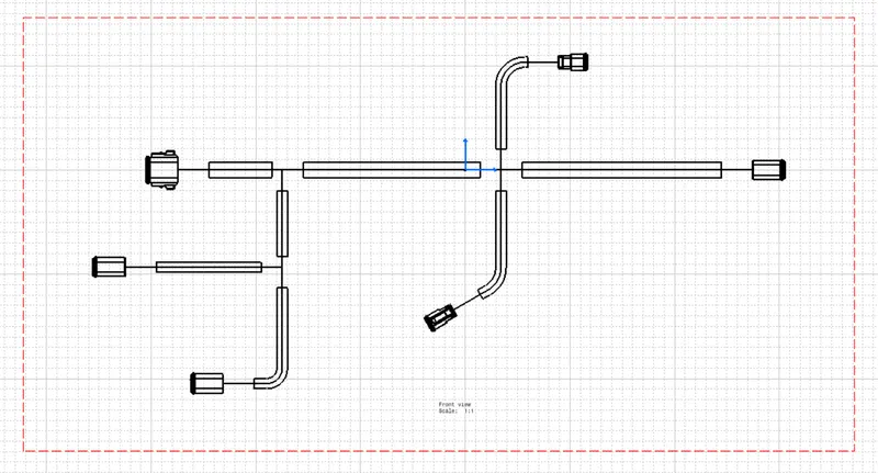
AS shown we made sure that as per objective of project the bundle segment and protective covering are represented differently:
SINGLE LINE -BUNDLE SEGMENT
DOUBLE LINE-PROTECTIVE COVERING