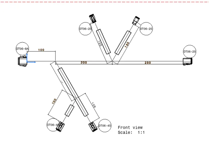
Wiring harness design in CATIA V5 - 3D modeling Week 7 Challenge
STEPS;-
- Define cavity connecction point
- define connector as a elctrical component
- create a product file which is "Assembly_Wiring_Harness_context"
- Inside Assembly_Wiring_Harness_context I have create one more product file which is "Different_Connector_wiring"
- Copy all connector inside Different_Connector_wiring
- Arrange the all connecctor accordind to Shown daigram
- Convert "Different_Connector_wiring" product as geometrical bundle
- Creating routing through multi branchable document
- adding branch point where required
- create cataloge for protective covering
- Add the cot tube where challenge said
- using measure command measure the bundle length which is shown in image
- Create a product file which name is flatting product.
- Go to Electrical harnessign flatting workbench and open the product file of week 4 challenge which is "Different wirirng connector context"
- Using extract command in flatting workbench and select the different wiring connector product file.
- Using fltten command flatting the wire branch and save the file in respected folder.
- Using rotate,Quick roll and junction command we adjust the wire branch but in this proct file there no need so we ignore this.
- Create a drawing file and save this drwaing file on respective folder and using front view command we select respective face where wire was flatten.
- Adujust the drawing view and orientaion and select the drawing and adjust the properties of the drawing for which connector, cot tube and wire visible properly.
- Using measeure command measure the wire dimenssion and using ballon command create the name the respective connecctor.
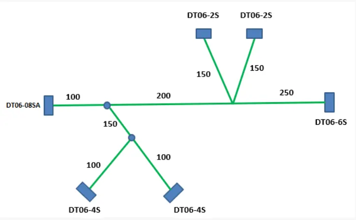
PRODUCT FILE IMAGE
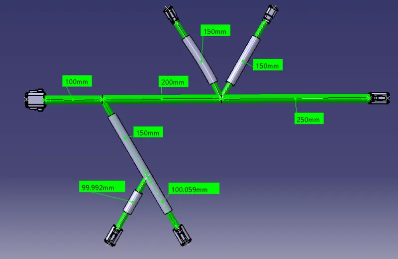
FLATTENING VIEW IMAGE
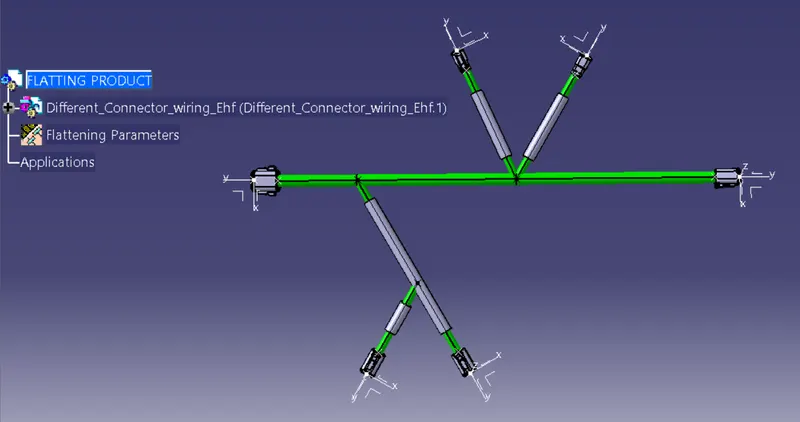
DRWAING VIEW IMAGE